
Device and method for testing water permeability resistance of lateral restriction-free concrete joint

A technology of test device and test method, applied in measurement device, permeability/surface area analysis, suspension and porous material analysis, etc., can solve problems such as increasing the extrusion force between concretes and failing to reflect the impermeability of joints. , to achieve the effect of eliminating the restraint effect of the hoop

Active Publication Date: 2015-03-25
SOUTHWEST JIAOTONG UNIV
View PDF9 Cites 8 Cited by
  • Summary
  • Abstract
  • Description
  • Claims
  • Application Information

AI Technical Summary

Problems solved by technology

The main problem of using this method is: in order to prevent the concrete test block from being pushed out by the water pressure, the steel sleeve on the concrete impermeability instrument is a round table (small at the top and large at the bottom), so when installing the concrete impermeability test block and In the process of adding water pressure from the bottom, a hoop constraint will be formed between the concrete impermeability test block and the steel sleeve, which will increase the extrusion force between the new and old concrete, resulting in different degrees of closure of the joints, which cannot reflect The impermeability of the joints under actual working conditions

Method used


Image

  • Device and method for testing water permeability resistance of lateral restriction-free concrete joint
  • Device and method for testing water permeability resistance of lateral restriction-free concrete joint
  • Device and method for testing water permeability resistance of lateral restriction-free concrete joint

Examples


Embodiment

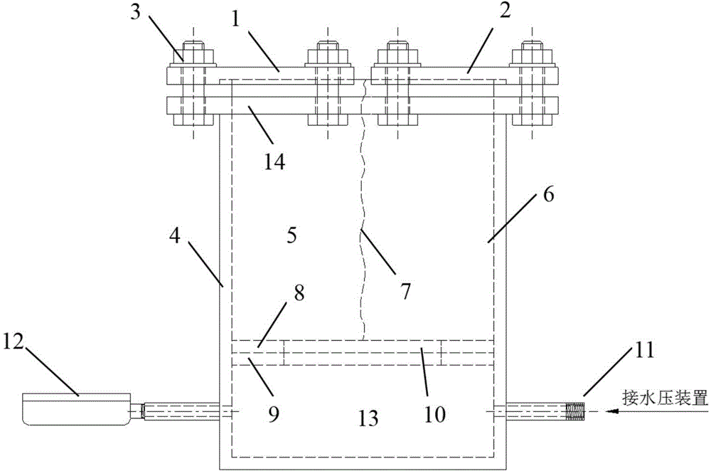
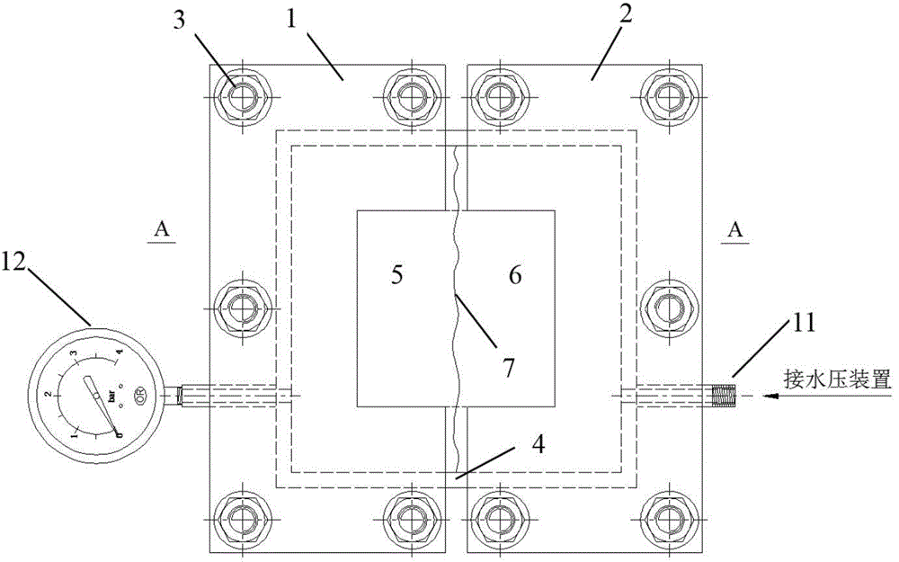
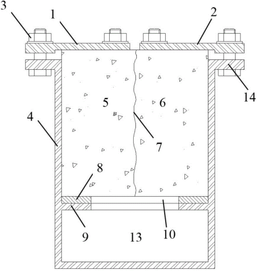
[0020] Such as Figure 1-Figure 3 As shown, a kind of specific implementation mode of the present invention is, can realize the anti-water penetration performance test under the state of no lateral restraint of new and old concrete joints, and its implementation steps are as follows:

[0021] (1) Make half a concrete test block in the concrete cube test form to simulate the old poured concrete, after demoulding, its surface 7 is processed, and then cured for 28 days;

[0022] (2) Put the old concrete test block into the concrete cube test form, with the old and new concrete joint interface 7 facing up, pouring concrete on the upper part to simulate the newly poured concrete, forming a complete concrete joint impermeability test block 5, and curing for 28 days after demoulding;

[0023] (3) The test device described in the technical solution of the present invention is connected to the hydraulic device 11 and the hydraulic gauge 12, and the elastic sealing gasket 8 is installed...


PUM


Abstract

The invention discloses a device and a method for testing the water permeability resistance of a lateral restriction-free concrete joint. The device is used for testing the water permeability resistance of a test block at a new-old concrete joint part, and comprises a double-layer square cylinder 4 used for placing a new-old concrete joint anti-permeability test block 5, wherein the bottom of the square cylinder is sealed; an outer flange 14 is arranged at the upper opening of the square cylinder; an inner flange 9 with an intermediate opening 10 is arranged at the lower part of the square cylinder; the square cylinder is separated into two parts, namely a test block compartment 6 and a water inlet compartment 13 by virtue of the inner flange; an elastic sealing gasket 8 is arranged on the inner flange; a left cover plate 1 and a right cover plate 2 are fixedly pressed on the outer flange of the square cylinder by virtue of fastening bolts 3; the water inlet compartment in the lower part of the square cylinder is connected with a water pressure device 11 and inlet water and is also connected with a water pressure gauge 12; and a viewing opening through which the water seepage condition is conveniently observed is formed between the left cover plate and the right cover plate according to the shape and the area of the concrete joint. According to the device and the method disclosed by the invention, the water permeability resistance of the new-old concrete joint part can be realized under the lateral restriction-free action.

Description

technical field [0001] The invention relates to a test device for the water penetration resistance of the joints of new and old concrete structures caused by construction intervals. Background technique [0002] In the civil engineering industry, there are parts where there are joints in the concrete structure due to the construction interval, such as the concrete joints and post-casting strips in the basement, the subway station structure with a laminated wall structure, and the joints of the fabricated underground structure Parts, concrete stubble parts of underground passages, post-repair parts of other engineering structures, etc. When these engineering structures are located below the groundwater level, these joints are often the places where the leakage is relatively concentrated during the operation and use stage, which has a great impact on the later use of the structure and the durability of the concrete, and will also cause certain damage. In serious cases, it may...

Claims


Application Information

Patent Timeline
Patent Type & Authority Applications(China)
IPC IPC(8): G01N15/08
Inventor 蒋雅君杨其新刘东民盛草樱杨娟邱品茗
Owner SOUTHWEST JIAOTONG UNIV
Learn More