

A constant current control circuit for an automobile ignition module
A technology of constant current control circuit and ignition module, applied in ignition controller, spark ignition controller, engine ignition and other directions, can solve the problems of troublesome debugging, poor temperature characteristics, many additional components, etc., to achieve simple circuit design, The effect of good temperature characteristics and a small number of components
- Summary
- Abstract
- Description
- Claims
- Application Information
AI Technical Summary
Problems solved by technology
Method used
Image

Examples
Embodiment Construction
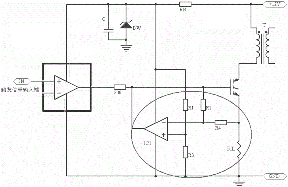
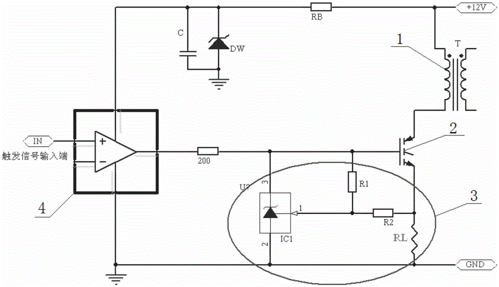
[0015] see image 3 , 4 , reflecting a specific application structure of the present invention. The shown constant current circuits all include an ignition coil 1 , a switching power tube 2 , and a constant current control circuit 3 , and the active module constant current circuit is also provided with a signal processing circuit 4 . The constant current control circuit 3 is composed of a three-terminal programmable voltage regulator IC1, programming resistors R1, R2, and current sampling resistor RL: the cathode of the three-terminal programmable voltage regulator is connected to the base of the switching power tube (control pole ), the reference end of the three-terminal programmable voltage regulator tube is connected to the voltage dividing point composed of programming resistors R1 and R2; the other end of the resistor R1 is connected to the base of the switching power tube, and the other end of the resistor R2 is connected to the current sampling resistor RL; the three-...
PUM
 Abstract
Description
Claims
Application Information