A constant flow pump back cover

A constant flow pump and valve hole technology, which is applied to pumps, pump components, and parts of pumping devices for elastic fluids, etc., can solve problems such as unsatisfactory constant flow effects, many processing procedures, and heavy weight of the back cover. Improve the opening and closing sensitivity, reduce the processing surface and processing steps, and reduce the weight

Inactive Publication Date: 2016-06-01
洛阳东方动力机械有限公司
View PDF7 Cites 0 Cited by
  • Summary
  • Abstract
  • Description
  • Claims
  • Application Information

AI Technical Summary

Problems solved by technology

[0002] The back cover of the constant flow pump in the prior art has a structure such as Figure 7 As shown, the center line of the oil outlet 4 of the back cover for the constant flow pump and the center line of the valve hole 2 for installing the safety valve are arranged in the middle of the back cover of the constant flow pump in parallel. Before covering the oil outlet 4, it needs to pass through a longer section of oil outlet channel 16 that communicates with the oil outlet 4 of the rear cover. While the oil inlet hole 5 of the back cover is connected, there is also an opening opposite to the oil outlet 4 of the back cover that needs to be sealed with a screw plug III15. Such a structure not only has a loose structure, but also makes the back cover heavy and difficult to process. There are many surfaces, many processing procedures, high cost, and because the screw plug III15 needs to be sealed, it is easy to cause seal leakage, resulting in unsatisfactory constant current effect

Method used


Image

  • A constant flow pump back cover
  • A constant flow pump back cover
  • A constant flow pump back cover

Examples


Embodiment Construction

[0019] The present invention will be described in further detail below in conjunction with the accompanying drawings and specific embodiments.

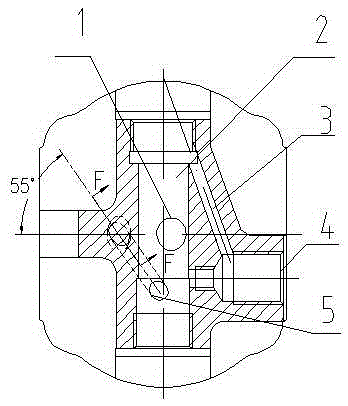
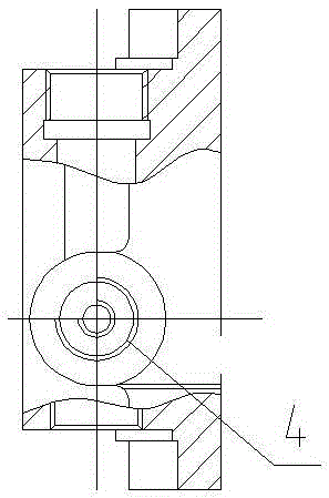
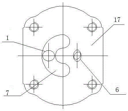
[0020] Such as Figure 1 to Figure 5 As shown, a constant flow pump back cover, the constant flow pump back cover is provided with a valve hole 2 for installing a safety valve, a moon groove 7 for oil inlet of the constant flow pump and a hole for oil output of the constant flow pump The back cover oil inlet and the back cover oil outlet 4, the moon groove 7 is set on the inner surface 17 of the back cover (that is, the joint surface between the back cover and the pump body), and the valve hole 2 is set on the back cover The opposite side of the joint surface of the cover and the pump body is the outer side of the back cover, and is located in the middle of the side. The valve hole 2 is a through hole, and its two ends are respectively provided with threads for installing screw plugs. The center line of the hole 2 is consistent with ...


PUM


Abstract

A constant flow pump rear cover is provided with a valve hole, a moon groove for inputting oil of a constant flow pump and a rear cover oil output port for outputting the oil into the constant flow pump. The moon groove is formed in the inner side face of the rear cover, the valve hole is formed in the outer side face of the rear cover, and the central line of the valve hole is consistent with the diameter direction in which an opening of the moon groove faces. On the inner side face, the oil input port end of a rear cover oil input hole communicated with the valve hole, the central axis of the rear cover oil input hole is arranged in an inclined mode and is communicated with one end of a valve hole installation safety valve body, the rear cover oil output port is formed in the lateral face of the rear cover opposite to the moon groove, wherein the rear cover oil output port is communicated with the valve hole, and the central line of the rear cover oil output port is perpendicular to the central line of the valve hole. A safety oil leakage hole is formed between the rear cover oil output port and the upper end of the valve hole, and an oil return hole is formed between the middle of the valve hole and the moon groove. Due to the fact that the rear cover oil output port is arranged perpendicular to the valve hole, the length of an oil output channel is shortened, consumption of a raw material is reduced, the weight of a product is reduced, production cost is finally reduced, and constant flow performance of the pump is improved.

Description

technical field [0001] The invention relates to a pump cover, in particular to a constant flow pump back cover. Background technique [0002] The back cover of the constant flow pump in the prior art has a structure such as Figure 7 As shown, the center line of the oil outlet 4 of the back cover for the constant flow pump and the center line of the valve hole 2 for installing the safety valve are arranged in the middle of the back cover of the constant flow pump in parallel. Before covering the oil outlet 4, it needs to pass through a longer section of oil outlet channel 16 that communicates with the oil outlet 4 of the rear cover. While the oil inlet hole 5 of the back cover is connected, there is also an opening opposite to the oil outlet 4 of the back cover that needs to be sealed with a screw plug III15. Such a structure not only has a loose structure, but also makes the back cover heavy and difficult to process. There are many surfaces, many processing procedures, hig...

Claims


Application Information

Patent Timeline
Patent Type & Authority Patents(China)
IPC IPC(8): F04D29/40F04D29/06
Inventor 周斌李欢欢葛彦卫
Owner 洛阳东方动力机械有限公司
Why Eureka
Try Eureka