LED downlight light source integrated circuit and led downlight

An LED downlight and integrated circuit technology, which is applied in the field of LED downlight source integrated circuits, can solve the problems of efficiency, constant current performance dimming effect defects, high assembly process requirements, increased component consumption, etc., and achieves superior power conversion. Efficiency and dimming effect, low cost, effect of stable constant current performance

Active Publication Date: 2018-01-19
FOSHAN TOPDAY OPTOELECTRONICS TECH
View PDF5 Cites 0 Cited by
  • Summary
  • Abstract
  • Description
  • Claims
  • Application Information

AI Technical Summary

Problems solved by technology

The driving circuit and the LED module are designed separately, and the driving circuit part needs to be designed with a protective case to protect the components of the driving circuit, and then connected to the LED module through wires. This design not only increases the amount of components used, but also It has high requirements for assembly process, but with the continuous reduction of cost in the market, this design can no longer meet the needs of the existing market
[0003] In this regard, a new LED downlight using a new scheme has appeared on the market. This scheme is called DOB. The downlight using the DOB scheme is to configure the LED light source and the driving circuit on the same aluminum substrate. Because the driving circuit and the LED The integrated setting of the light source effectively reduces the technical problems of many downlight parts, complicated assembly process and high cost
The drive circuit part of the current DOB scheme is a high-voltage linear constant current circuit, but the high-voltage linear constant current circuit has certain defects in terms of efficiency, constant current performance, and dimming effect.

Method used


Image

  • LED downlight light source integrated circuit and led downlight
  • LED downlight light source integrated circuit and led downlight
  • LED downlight light source integrated circuit and led downlight

Examples


Embodiment Construction

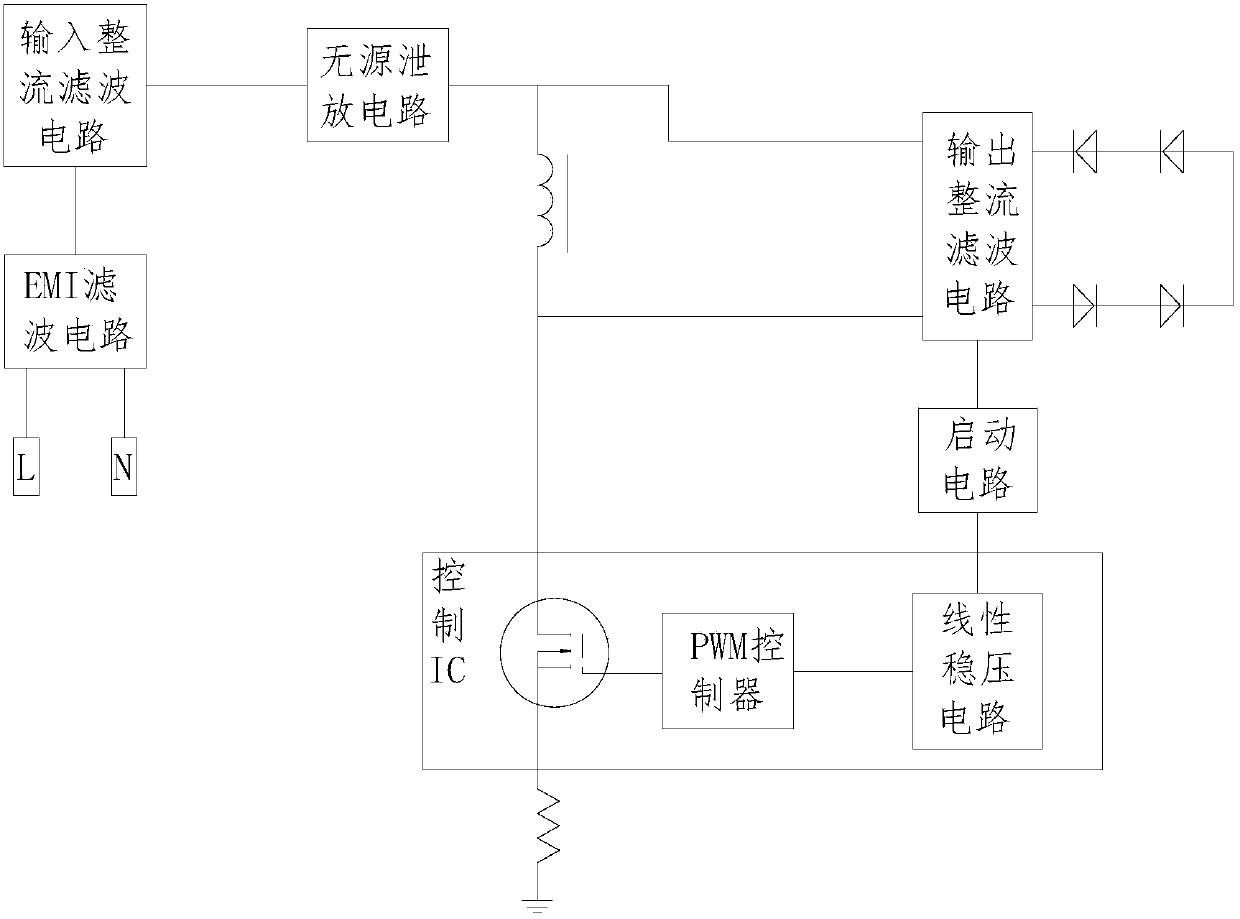
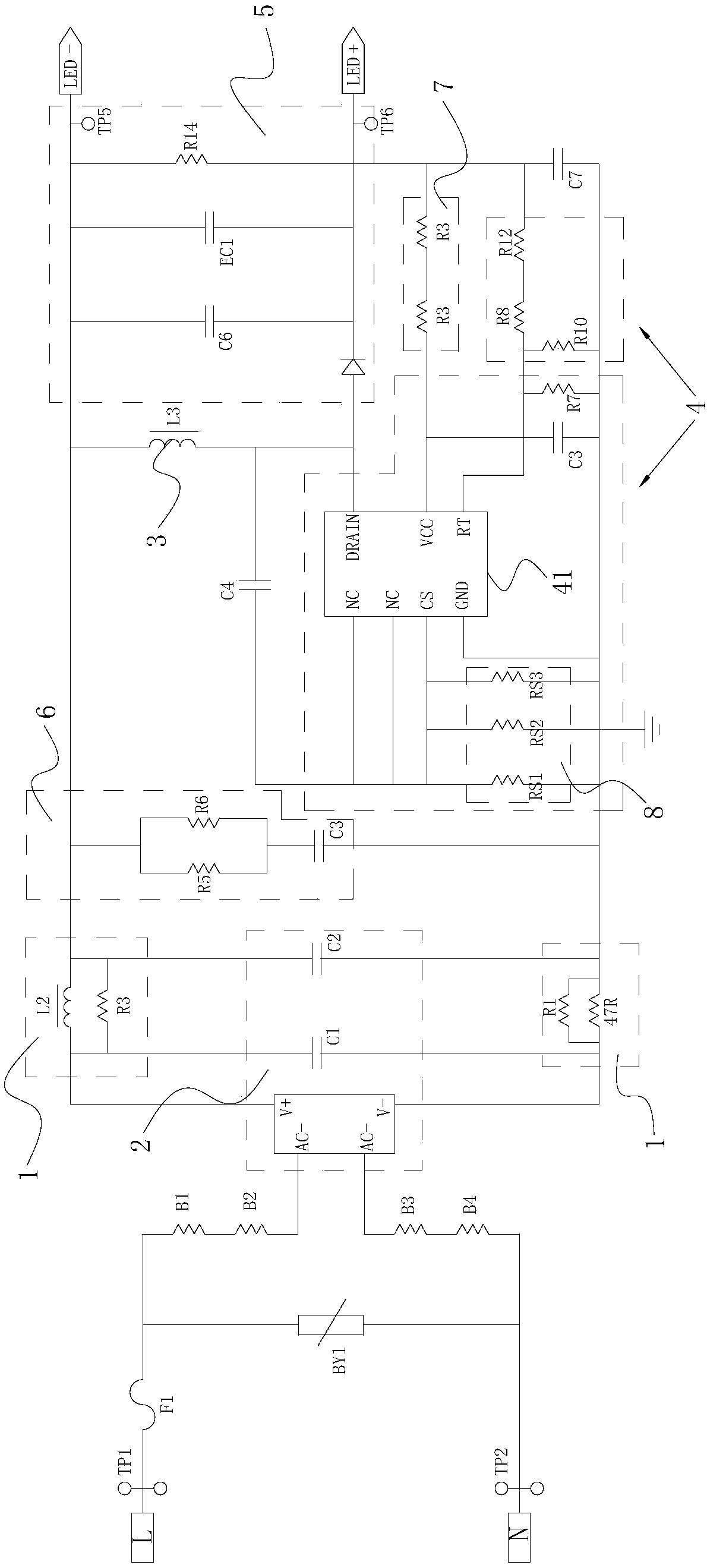
[0022] see Figure 1 to Figure 2 , an LED downlight light source integrated circuit provided by the present invention includes an EMI filter circuit 1, an input rectification filter circuit 2, a power inductor 3, a control IC4 and an output rectification filter circuit 5; the EMI filter circuit 1 is used to filter out AC Interference signals in the input electricity, the output end of the EMI filter circuit 1 is connected to the input end of the input rectification filter circuit 2, and the input rectification filter circuit 2 is used to convert the alternating current after filtering out the interference signal into direct current; The control IC4 includes a MOS transistor (not shown), a PWM controller 41 and a linear voltage regulator circuit, one end of the power inductor 3 is connected to the output end of the input rectification filter circuit 2, and the other end is connected to the MOS Tube connection, and the power inductor 3 outputs an oscillating voltage to the outpu...


PUM


Abstract

The LED downlight light source integrated circuit provided by the present invention adopts the DOB scheme integrating the switching power supply circuit and the LED, and integrates the MOS tube, the PWM controller and the linear voltage regulator circuit into one control IC, so that the original power supply circuit can be saved. A large number of circuit devices are added to make the driving circuit very small, so that the LED lamp bead and the driving circuit are packaged on the same aluminum substrate at the same time, which greatly saves the BOM cost. At the same time, the LED downlight light source integrated circuit using the switching power supply circuit is also It combines stable constant current performance, superior power conversion efficiency and dimming effect. The structure of the LED downlight using the integrated circuit of the present invention is simple, so that the assembly of the LED downlight is simpler, the cost is lower, and it has stable constant current performance, superior power conversion efficiency and dimming effect.

Description

technical field [0001] The invention relates to an LED downlight light source integrated circuit and an LED downlight. Background technique [0002] At present, the existing LED downlights are mainly composed of heat dissipation components, LED modules, driving circuits, light expansion boards and the like. The driving circuit and the LED module are designed separately, and the driving circuit part needs to be designed with a protective case to protect the components of the driving circuit, and then connected to the LED module through wires. This design not only increases the amount of components used, but also The requirements for the assembly process are relatively high, but as the market continues to compress costs, this design can no longer meet the needs of the existing market. [0003] In this regard, a new LED downlight using a new scheme has appeared on the market. This scheme is called DOB. The downlight using the DOB scheme is to configure the LED light source and...

Claims


Application Information

Patent Timeline
Patent Type & Authority Patents(China)
IPC IPC(8): H05B33/08F21K9/23F21V19/00F21Y115/10H05B44/00H05B45/10H05B45/325H05B45/345H05B45/36H05B47/165
CPCF21V19/001H05B45/00
Inventor 何承龙屈经斌汪兴海季超潘世豪
Owner FOSHAN TOPDAY OPTOELECTRONICS TECH
Why Eureka
Try Eureka