Self-propelled fan high bypass ratio turbofan engine with inner ring air turbine

A turbofan engine, air turbine technology, applied in the direction of machine/engine, jet propulsion, etc., can solve the problems of inability to contribute to the economy, difficult to manufacture fans and turbines, complex rotor dynamics, etc. Risk and development cost, the effect of solving the speed mismatch problem and avoiding the rotor dynamics problem

Active Publication Date: 2016-04-20
NANJING UNIV OF AERONAUTICS & ASTRONAUTICS
View PDF6 Cites 0 Cited by
  • Summary
  • Abstract
  • Description
  • Claims
  • Application Information

AI Technical Summary

Problems solved by technology

[0004] These methods have alleviated the speed mismatch problem of the turbofan engine with a large bypass ratio to a certain extent, but there are also some deficiencies: (1) The turbofan engine is driven by a gear, and the low-pressure turbine drives the fan after being decelerated by a gear reducer, so that The speed of the low-pressure shaft matches the speed of the fan rotor. However, due to the huge transmission power and large speed ratio of the gear reducer, its design is very difficult, and there are problems of reliability and life. It is often used as a turbofan engine with a large bypass ratio. The bottleneck of development restricts the increase of bypass ratio of this type of engine; (2) The use of three-rotor turbofan engine can more reasonably distribute power and match speed among fans, high and low pressure compressors and high, low and medium pressure turbines. The turbine only needs to drive the fan instead of the low-pressure compressor, so its speed can be further reduced
However, even though the increase in the outer diameter of the low-pressure turbine caused many problems, there is still a large rim speed difference between the diameter of the high-bypass fan rotor and the low-pressure turbine (the speed mismatch problem is only alleviated but not resolved)
In addition, the structure of the three-rotor turbofan engine is often very complex, and there are complex rotordynamic problems in the three concentric shafts. These factors make it possible for only a few engine companies to adopt and master this technology; (3) adopt the rear fan turbofan The engine, its independent low-pressure turbine drives the fan, the fan can use a lower speed, and the turbine work does not need to be forwarded through the rotating shaft, avoiding the concentric shaft system with complex structure, but its disadvantages are also significant: on the one hand, the integration of different materials The fans and turbines are difficult to process and manufacture, and require complex structures for sealing to prevent gas from leaking to the outer body; Contribute to the improvement of content economy
These shortcomings make the turbofan engine in the form of rear fan not widely used after the early development of turbofan engine, and gradually fade out of people's field of vision

Method used


Image

  • Self-propelled fan high bypass ratio turbofan engine with inner ring air turbine
  • Self-propelled fan high bypass ratio turbofan engine with inner ring air turbine
  • Self-propelled fan high bypass ratio turbofan engine with inner ring air turbine

Examples


Embodiment

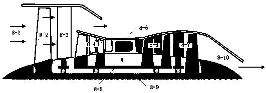
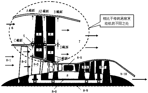
[0035] For a dual-rotor turbofan engine, its total flow is 95.3kg / s, the internal total pressure ratio is 23, the outer culvert total pressure ratio is 1.7, the bypass ratio is 5.3, the maximum thrust is 2546.6dN, and the corresponding fuel consumption rate is 1.05kg / (dN *h). After remodeling and designing according to the method proposed by the present invention, the total pressure ratio of the outer culvert is 1.2 and the bypass ratio is 14.3. Through the overall performance calculation, the maximum thrust is 3703.1dN, corresponding to the fuel consumption rate of 0.72kg / (dN*h), and the thrust is higher than the prototype The turbofan engine has increased by 45.4%, fuel consumption has been reduced by 31.4%, and its performance has been greatly improved.


PUM


Abstract

The invention relates to a self-driven fan large-bypass-ratio turbofan engine with an inner loop air turbine and a design method. The self-driven fan large-bypass-ratio turbofan engine is characterized in that an outer bypass part is provided with a self-driven fan rotor with a larger bypass ratio and with an inner loop air turbine, the rotor comprises an auxiliary bypass fan rotor (1), an air-driving turbine rotor (3) and a rotating medium casing (5); an auxiliary bypass fan stator (2) is arranged on the downstream of the auxiliary bypass fan rotor (1); an air-driving turbine stator (4) is arranged on the downstream of the air-driving turbine rotor (3). The self-driven fan large-bypass-ratio turbofan engine has advantages: (1) while the bypass ratio is increased, the problem of the large-bypass-ratio turbofan that the rotation speed of the fan is not matched with that of the low voltage rotor can be avoided; (2) compared with the scheme of a gear turbofan engine (GTF) and a three-rotor turbofan engine for solving the mismatch problem of the rotation speed, the structure is simplified; (3) the self-driven fan large-bypass-ratio turbofan engine can be improved on the basis of the existing two-rotor turbofan engine, so that the technical risk and research cost can be reduced, and the research period can be shortened.

Description

Technical field [0001] The technology of the present invention belongs to the field of new concept turbofan engines, and mainly relates to the design concept, main structure arrangement and aerodynamic design method of a self-driving fan with an inner ring air turbine and a large bypass ratio turbofan engine. The present invention proposes to change the way of transferring work from the inner duct part of the turbofan engine to the outer duct part from the traditional mechanical shaft torque transmission to the fan using the air flow to drive itself, that is, the original turbofan engine fan rotor outlet is pressurized to drive the air flow. The fan air turbine is driven to perform work, and the additional duct fan rotor fixedly connected to it is driven to rotate through the intermediate casing, so as to realize the supercharging of the additional duct. Background technique [0002] For a long time, the development of aero engines has been aimed at pursuing high thrust-to-weight...

Claims


Application Information

Patent Timeline
Patent Type & Authority Patents(China)
IPC IPC(8): F02K3/06F02K5/00
Inventor 黄国平陆惟煜傅鑫向鑫马文孝
Owner NANJING UNIV OF AERONAUTICS & ASTRONAUTICS
Why Eureka
Try Eureka