Non-contact force measuring device and method

A force measuring device and non-contact technology, applied in the field of fluid mechanics, can solve problems such as the influence of the measured dynamic parameters and the influence of the information of the flow field.

Active Publication Date: 2017-01-25
SHANGHAI JIAO TONG UNIV
View PDF1 Cites 0 Cited by
  • Summary
  • Abstract
  • Description
  • Claims
  • Application Information

AI Technical Summary

Problems solved by technology

However, this technology still needs to connect the insects with the measurement module, and the measurement module will not only affect the measured dynamic parameters, but also affect the information of the flow field in the observation box

Method used


Image

  • Non-contact force measuring device and method
  • Non-contact force measuring device and method
  • Non-contact force measuring device and method

Examples


Embodiment 1

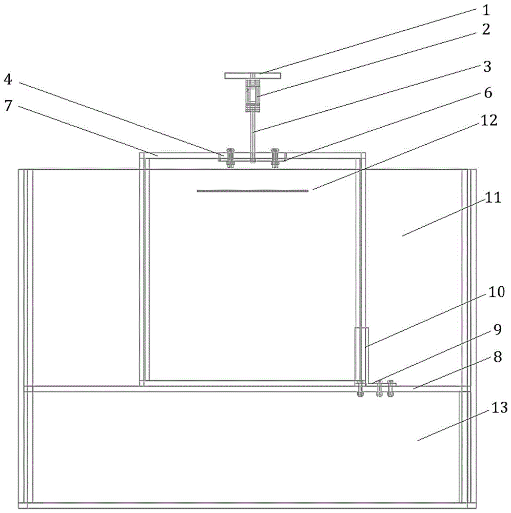
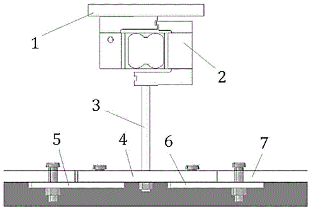
[0024] Such as figure 1 As shown, in this embodiment: the sensor 2 is fixed on the upper fixing plate 1, the lower end of the sensor 2 is connected to the connecting rod 3, and the connecting rod 3 is connected to the detection chamber 7 through the connecting plate 4 and the lower fixing plates 5,6.

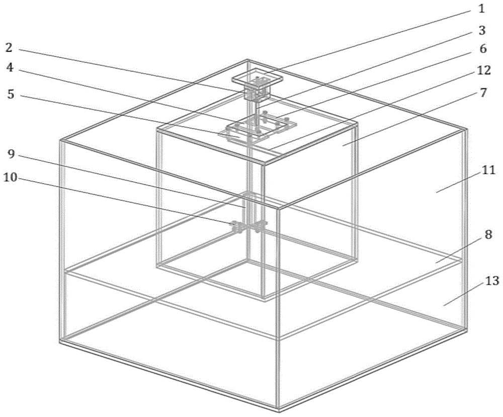
[0025] The detection chamber 7 is placed on the support plate 8 by using the first and second positioning plates 9 , 10 , and the support plate 8 floats in the casing 11 . Therefore, the experimental device can be used to measure the fluid force in the detection chamber 7 that the plate 12 is subjected to when it falls freely.

[0026] The first and second positioning plates 9 and 10 are L-shaped structures and are respectively arranged on different sides of the detection chamber 7 .

[0027] The sensor 2 is connected with the connecting rod 3 at the lower end by threads, and the connecting rod 3 is connected with the force-bearing member below.

[0028] The lower fixing plate...


PUM


Abstract

The invention provides a non-contact force measuring device and a non-contact force measuring method in the field of fluid mechanics. The device comprises a detection cavity in a housing, wherein a supporting plate for holding the detection cavity is arranged in the housing; a detection media is put under the supporting plate; a sensing mechanism is arranged at the top of the detection cavity and the bottom of the detection cavity is fixedly connected with the supporting plate; an object to be tested is arranged in the detection cavity; the sensing mechanism comprises an upper fixed plate fixed in height, a lower fixed plate connected to the top of the detection cavity, and a sensor and a connecting rod both orderly arranged between the upper and lower fixed plates. The non-contact force measuring device is capable of measuring the fluid acting force on an object moving inside a flow field outside the flow field, and meanwhile, obtaining the corresponding flow field structure according to the related image technology.

Description

technical field [0001] The invention relates to a detection technology in the field of fluid mechanics, in particular to a device and a method for measuring fluid force on an object without contacting it. Background technique [0002] Biopropulsion has always been a research hotspot in bionics, and people have invented the current aircraft after being inspired by the flight of birds. At present, the main research objects of biopropulsion include the flapping motion of birds, insects, etc., and the swimming of fish, etc., and one of the main goals of studying these biological motions is to study their dynamic characteristics, that is, what they do when they move. The fluid force received can optimize and improve the existing aircraft. [0003] Existing literature Sanjay P. Sane and Nathaniel P. Jacobson (2006) in Induced airflow in flying insects, (The Journal of Experimental Biology 209, 43‐56), and HirokiSugiura, Michael H. Dickinson (2009) in The generation of forces and ...

Claims


Application Information

Patent Timeline
Patent Type & Authority Patents(China)
IPC IPC(8): G01L5/00G01M10/00
Inventor 秦苏洋黄文涛王福新傅翔刘洪向阳张淼毛安寅
Owner SHANGHAI JIAO TONG UNIV
Why Eureka
Try Eureka