Bending machine

A bending machine and bending mechanism technology, applied in the field of bending machines, can solve problems such as poor continuity, low production efficiency, and complex structure, and achieve rapid prototyping and improve production efficiency.

Active Publication Date: 2015-05-27
OMS MASCH CO LTD
View PDF5 Cites 22 Cited by
  • Summary
  • Abstract
  • Description
  • Claims
  • Application Information

AI Technical Summary

Benefits of technology

The present invent describes two different ways for making things like plates that are bent into shapes called U shape when they're being used on an assembly line. This reduces the time it takes to change between forms without having to stop working over all its parts again after each use. Additionally, this design allows for quicker formation by create shaping patterns instead of traditional methods such as cutting them out from plate material beforehand.

Problems solved by technology

This patented technical problem addressed in this patents relates to improving the manufacturing of heat exchange devices such as tube bundles used for coolers. Current methods involve multiple steps involving moving tools between different locations during assembly, resulting in slowdowns and reduced productivity due to frequent changes needed when changing from one location to another.

Method used


Image

  • Bending machine
  • Bending machine
  • Bending machine

Examples


Embodiment Construction

[0033] The present invention will be further described in detail below in conjunction with the accompanying drawings and specific embodiments.

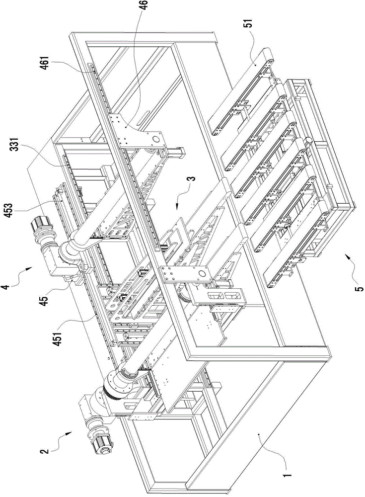
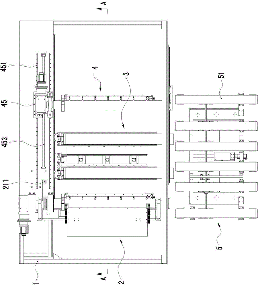
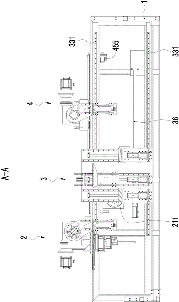
[0034] Such as Figure 1 to Figure 4 As shown, a bending machine includes a frame 1, a first bending mechanism 2 mounted on the frame 1 capable of bending the rear section of the workpiece, and a follower mechanism 3 mounted on the frame capable of carrying the workpiece , also includes a second bending mechanism 4 that is arranged on the frame 1 and can bend the front section of the workpiece, the follow-up mechanism 3 is located between the first bending mechanism 2 and the second bending mechanism 4 . When the workpiece is fed into the bending machine, the workpiece is fed along the transverse direction and enters the first bending mechanism 2, the follower mechanism 3 and the second bending mechanism 4 in sequence, and the workpiece can be sent into the bending machine through the automatic feeding equipment.

[0035] Such as F...


PUM


Abstract

The invention relates to a bending machine, which comprises a machine frame, a first bending mechanism, a following mechanism and a second bending mechanism, wherein the first bending mechanism is arranged on the machine frame and can be used for bending a workpiece, the following mechanism is arranged on the machine frame and can carry the workpiece, the second bending mechanism is arranged on the machine frame and can be used for bending the workpiece, and the following mechanism is positioned between the first bending mechanism and the second bending mechanism. Compared with the prior art, the bending machine has the following advantages that the first bending mechanism and the second bending mechanism are adopted for respectively bending the front section and the back section of the workpiece, the number of times for repeatedly positioning the workpiece in the bending process can be reduced, the U shape or G shape forming can be conveniently realized, in addition, the fast forming is realized, and the production efficiency is improved.

Description


Claims


Application Information

Patent Timeline
Owner OMS MASCH CO LTD
Why Eureka
Try Eureka