
Straight stroke mechanism of multi-turn electric actuator

An electric actuator and straight-stroke technology, which is applied in the improved invention field of the straight-stroke mechanism, can solve problems such as potential safety hazards, damaged valves, losses, etc., and achieves the effect of eliminating hidden dangers of damage, simple structure, and compact structure

Active Publication Date: 2015-05-27
ZHEJIANG AOXIANG AUTO CONTROL TECH CO LTD
View PDF9 Cites 2 Cited by
  • Summary
  • Abstract
  • Description
  • Claims
  • Application Information

AI Technical Summary

Problems solved by technology

However, since the valve is installed in a concealed state on the pipeline, it cannot be seen from the outside that the valve is activated. Therefore, when a power failure requires manual control, the staff cannot control the travel of the screw, that is, the state of the valve. This kind of blind operation has great safety hazards; moreover, when the electrical limit is adjusted, the stroke of the screw rod of the linear travel mechanism is different from the preset one, and the valve stem will be pulled too high, causing the valve stem to pull If it is damaged, it may even pull the valve stem out of the valve body, resulting in unimaginable consequences, or push the valve stem down too much or even bend the valve stem, both of which will damage the valve and cause serious losses

Method used


Image

  • Straight stroke mechanism of multi-turn electric actuator
  • Straight stroke mechanism of multi-turn electric actuator

Examples


Embodiment Construction

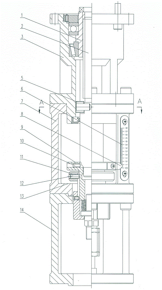
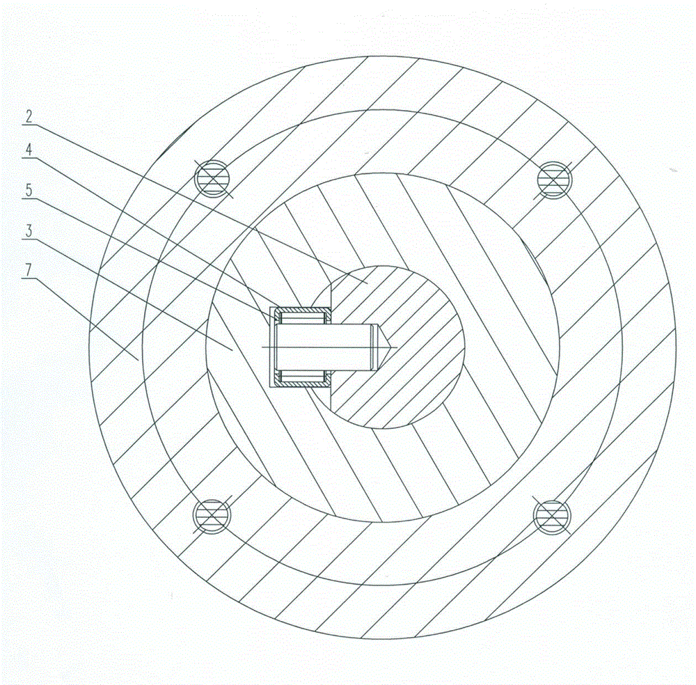
[0013] Referring to the accompanying drawings, the linear travel mechanism of this kind of multi-rotation electric actuator includes a bracket 7, a bearing seat 3, a screw rod 2 and a nut 1 matched with the screw rod, and the bearing seat 3 is installed on the bracket 7. The present invention can According to the length of the valve stem, a flange bracket 14 can be added under the bracket 7. When the valve stem is short, the screw rod 2 can be lengthened. Otherwise, a shorter screw rod can be used, so that it can be applied to more types of valves, and the processing is convenient and fast. Low cost; the nut 1 is connected to the main shaft of the multi-turn electric actuator, the screw 2 is vertically arranged in the bearing seat 3, and the inner surface of the bearing seat 3 is provided with a vertically arranged guide groove 4, the The screw 2 corresponding to the guide groove 4 is equipped with a matching needle bearing 5, the needle bearing 5 is placed in the guide groove ...


PUM


Abstract

The invention discloses an improved invention of a straight stroke mechanism of a multi-turn electric actuator. The straight stroke mechanism comprises a bracket, a bearing seat, a screw and a nut, wherein the nut is matched with the screw, the bearing seat is installed on the bracket, the nut is connected with a main shaft of the multi-turn electric actuator, the screw is vertically arranged in the bearing seat and moves in a straight line up and down, and the lower end of the screw passes through the bracket and then is connected with a valve rod of a valve. The straight stroke mechanism is characterized in that a displacement display assembly which is used for displaying the displacement of the screw is arranged on the bracket, a limiting plane is formed on the inner surface of the bracket, a limiting nut which is matched with the limiting plane of the bracket and is used for controlling the displacement of the screw is installed on the screw, and internal threads of the limiting nut are matched with the screw. According to the straight stroke mechanism, the screw is mechanically limited, so that the valve rod is prevented from being excessively pulled up or being pressed, the safety performance is improved, and the service life of the valve is prolonged.

Description

technical field [0001] The invention relates to an improved invention of a linear stroke mechanism, in particular to a linear stroke mechanism of a multi-rotation electric actuator. Background technique [0002] The straight stroke mechanism of the multi-turn electric actuator is the same as the opening and closing of the valve, that is, the screw rod of the straight stroke mechanism drives the valve stem to move, so as to realize the opening and closing of the valve. Most of the existing straight-stroke mechanisms use electrical limiters to control the stroke of the screw rod electrically, that is, to control the movement of the valve stem. However, since the valve is installed in a concealed state on the pipeline, it cannot be seen from the outside that the valve is activated. Therefore, when a power failure requires manual control, the staff cannot control the travel of the screw, that is, the state of the valve. This kind of blind operation has great safety hazards; mor...

Claims


Application Information

Patent Timeline
Patent Type & Authority Applications(China)
IPC IPC(8): F16K37/00F16K31/44
CPCF16K31/047F16K31/508F16K37/0083
Inventor 蔡东武
Owner ZHEJIANG AOXIANG AUTO CONTROL TECH CO LTD
Learn More