Reinforcing material for preventing punching shear, and construction method using same for areas where pillars join with slabs and spread foundations

A technology for strengthening components and construction methods, which is applied in the direction of basic structure engineering, building components, building reinforcements, etc., can solve problems such as increasing connection operations, increasing workload, and impact on the safety of plate-pillar joints, achieving reduction in thickness, The effect of reducing reinforcement ratio

Active Publication Date: 2015-06-17
KOREA INST OF CIVIL ENG & BUILDING TECH
View PDF10 Cites 0 Cited by
  • Summary
  • Abstract
  • Description
  • Claims
  • Application Information

AI Technical Summary

Problems solved by technology

Since this punching failure is brittle unlike other forms of failure, it has a fatal impact on the safety of the plate-pillar joint
[0004] As a method of reinforcing the plate-pillar junction in this structure, the method adopted has a supporting plate and a column head around the column, but the problem that it exists is that the mold for setting the supporting plate or the column head is cumbersome to manufacture, and Not very effective at enhancing performance either
[0007] However, the above-mentioned former background art has disadvantages of increased workload due to installation of GFRP poles and laying work of fiber-reinforced concrete, and increased construction costs due to fiber-reinforced concrete
In addition, the latter background art has a problem that since its structure is that the steel shear strip is welded to the pillar, it increases the connection work and has the possibility of causing a defect in the welded joint.

Method used


Image

  • Reinforcing material for preventing punching shear, and construction method using same for areas where pillars join with slabs and spread foundations
  • Reinforcing material for preventing punching shear, and construction method using same for areas where pillars join with slabs and spread foundations
  • Reinforcing material for preventing punching shear, and construction method using same for areas where pillars join with slabs and spread foundations

Examples


no. 1 approach

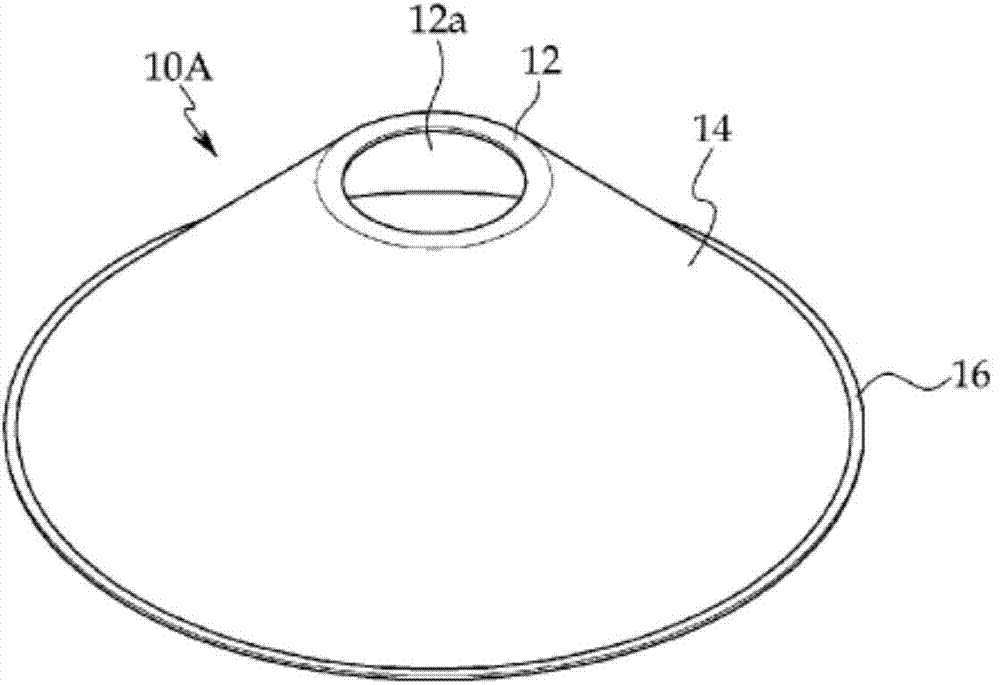
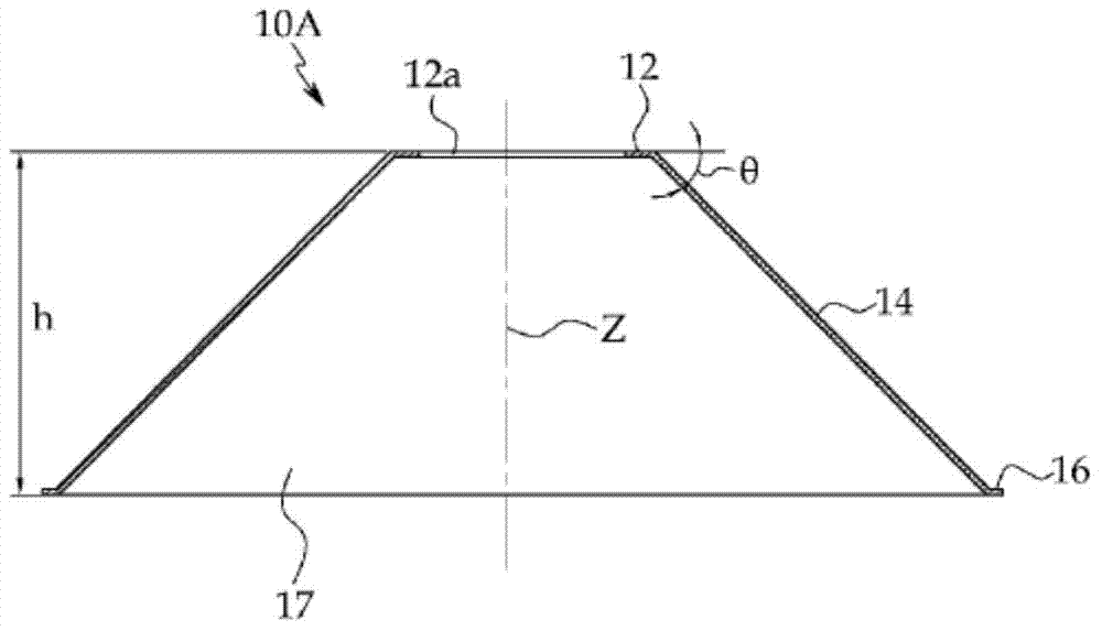
[0071] Figure 1a and Figure 1b In the figure, there is shown a punching resistance reinforcing member 10A according to the first embodiment. The punching resistance reinforcing member 10A is made of a metal material. For example, the punching resistance reinforcing member 10A can be made of steel. The punching resistance reinforcing member 10A is formed with: an upper disk 12 having a circular shape and a predetermined thickness; a skirt portion 14 extending from the outer periphery of the upper disk 12 and Gradually expand the cross-sectional area to the bottom, the skirt portion 14 determines the height h of the reinforcing member 10A for punching resistance; the concrete filling chamber 17, the concrete filling chamber 17 is hollow and the bottom of the concrete filling chamber 17 is open for Concrete is filled into the skirt portion 14 .

[0072] The thickness of the skirt portion 14 may be formed to be the same as or thicker than that of the upper disk 12 . The skir...

no. 2 approach

[0083] In the second embodiment, the same or equivalent parts as those in the first embodiment are described using the same symbols.

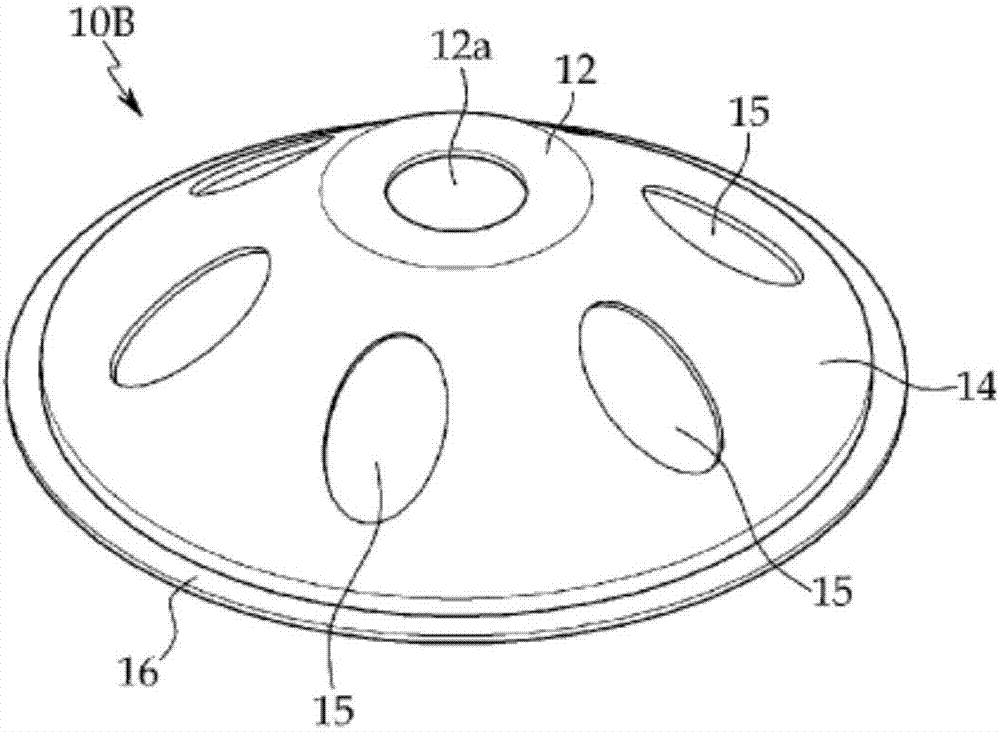
[0084] like Figure 7a and Figure 7b As shown, the punching resistance reinforcing member 10F according to the second embodiment is characterized by comprising: an upper disk 12 having a circular shape and having an upper concrete injection hole 12a in the center; a skirt portion 14, the The skirt part 14 extends from the circumference of the upper disc 12 and gradually expands the cross-sectional area from the top to the bottom; the concrete filling chamber 17 communicates with the upper concrete injection hole 12a and the bottom is open for the skirt The interior of the portion 14 is filled with concrete, and the skirt portion 14 is formed into a hemispherical shape by rotating a curved hypotenuse with a predetermined radius of curvature R around the central axis Z of the upper disc 12 for one revolution.

[0085]At this time, the upper co...


PUM


Abstract

The present invention provides: a reinforcing material for preventing punching shear, whereby punching shear is prevented by constituting a conical or semi-spherical reinforcing material, of which the cross-sectional size gradually increases downwards, such that the range of resistance to shearing forces is spread widely; and a construction method using same for areas where slabs join with pillars and where pillars join with spread foundations. The reinforcing material for preventing punching shear of the present invention comprises: an upper disk having a predetermined thickness; a skirt section which extends from the circumference of the upper disk, and widens from the top to the bottom as the cross sectional area gradually spreads in a zone of a fixed height; and a concrete charging chamber which opens towards the bottom such that the inside of the skirt section can be filled with concrete.

Description

technical field [0001] The present invention relates to reinforcement members for punching resistance For resisting punching at the junction of a plate and a pillar, or at a junction of a pillar and an enlarged foundation, particularly, a reinforcing member for punching resistance, a board and a pillar using the reinforcing member, and a junction of a pillar and an enlarged foundation A construction method that broadly expands the range of resistance to shear force by forming conical or hemispherical reinforcement members to resist punching Background technique [0002] The general forms of ordinary reinforced concrete structures include: slab, the slab The ground of each layer is formed and a predetermined area is provided; the pillar is used to support the plate and can transmit the self-weight of the structure and the use load generated by each layer to the foundation part. In such a reinforced concrete structure, a shear force acts on the joint between the plate and ...

Claims


Application Information

Patent Timeline
Patent Type & Authority Applications(China)
IPC IPC(8): E04C5/01E02D27/28
CPCE04C5/0645E02D27/28
Inventor 裵圭雄朴金成李相燮
Owner KOREA INST OF CIVIL ENG & BUILDING TECH
Why Eureka
Try Eureka