Serial-connection breath-type double-plate cabin solid carbon fuel cell stack and power generation method thereof

A fuel cell stack and fuel cell technology, applied in solid electrolyte fuel cells, fuel cell additives, fuel cell grouping, etc., can solve the problems of manufacturing difficulties, large circuit consumption in the battery, and excessive internal resistance.

Active Publication Date: 2015-06-24
ZHANGJIAGANG IND TECH RES INST CO LTD DALIAN INST OF CHEM PHYSICS CHINESE ACADEMY OF SCI
View PDF6 Cites 4 Cited by
  • Summary
  • Abstract
  • Description
  • Claims
  • Application Information

AI Technical Summary

Problems solved by technology

[0025] 1. The working efficiency of the battery is low, the cost is high, the structure is complicated, and the manufacturing is difficult;
[0026] 2. Low power density and high reaction temperature;
[0027] 3. The circuit in the battery consumes a lot, the internal resistance is too large, the utilization rate of water is not high, and the service life of the battery is short

Method used


Image

  • Serial-connection breath-type double-plate cabin solid carbon fuel cell stack and power generation method thereof
  • Serial-connection breath-type double-plate cabin solid carbon fuel cell stack and power generation method thereof
  • Serial-connection breath-type double-plate cabin solid carbon fuel cell stack and power generation method thereof

Examples


Embodiment 1

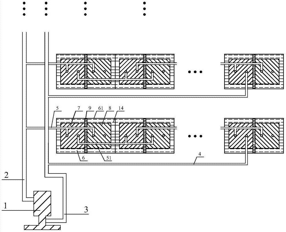
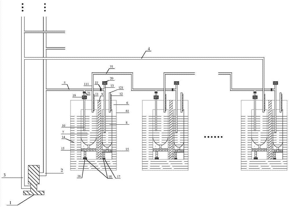
[0080] as attached Figure 1-4 As shown, the series-breathing double-plate warehouse solid carbon fuel cell stack includes a breathing device 1 and a battery unit 6, and a group of series-connected battery packs are connected to the breathing device. The low-pressure end of the low-pressure end is connected with the suction main pipeline 3, and the breath main pipeline is connected with an exhalation branch pipeline (5), and the suction main pipeline is connected with a suction branch pipeline 4;

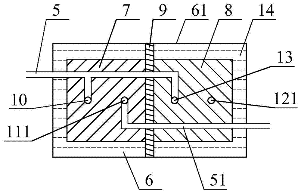
[0081] Each group of battery packs connected in series includes two groups of battery units connected in series to the breathing apparatus, wherein the upper ends of the anode air intake pipe 10 and the cathode air intake pipe 13 of the first group of battery units are all connected on the exhalation branch pipe 5, the first The upper end of the anode exhaust pipe 111 of the battery unit is connected to the gas connection pipe 51; the upper ends of the anode intake pipe 10 and the c...

Embodiment 2

[0094] This embodiment is identical with embodiment 1 basic structure, and different technical parameters are as follows:

[0095] (1) One hundred series battery packs are connected in parallel on the breathing apparatus, the high-voltage end of the breathing apparatus is connected to the main exhalation pipe 2, the low-pressure end of the breathing apparatus is connected to the main inhalation pipe 3, and the main exhalation pipe is connected to one hundred exhalation pipes. Air branch pipeline (5), inhalation main pipeline is connected with one hundred inhalation branch pipelines 4; each series series battery pack includes eighty groups of battery units connected in series to the breathing apparatus.

[0096] (2) The breathing device is a turbocharger, and the breathing frequency of the breathing device is 1000Hz.

[0097] (3) The small plate chamber of the anode plate storehouse is set as a spiral pipeline 15 .

[0098] (4) Electrode fillers 18 are arranged in the large ch...

Embodiment 3

[0100] This embodiment is identical with embodiment 1 basic structure, and different technical parameters are as follows:

[0101] (1) Six hundred series battery packs are connected in parallel on the breathing apparatus, the high-pressure end of the breathing apparatus is connected to the main exhalation pipeline 2, the low-pressure end of the breathing apparatus is connected to the main inhalation pipeline 3, and the main exhalation pipeline is connected to six hundred exhalation pipes. The gas branch pipeline (5), the suction main pipeline is connected with 600 suction branch pipelines 4; each group of series battery packs includes 400 groups of battery units connected in series to the breathing apparatus.

[0102] (2) The breathing device is a Roots booster, and the breathing frequency of the breathing device is 2Hz.

[0103] (3) The small plate chamber of the cathode plate chamber is set as a spiral pipeline 15 .

[0104] (4) The large plate chamber and the small plate c...


PUM

PropertyMeasurementUnit
current densityaaaaaaaaaa
particle size (mesh)aaaaaaaaaa

Abstract

The invention provides a serial-connection breath-type double-plate cabin solid carbon fuel cell stack and a power generation method thereof, belonging to the technical field of fuel cells. According to the cell stack, a plurality of groups of cell units are connected in series; each group of the cell units comprises an electrolyte cabin, a positive electrode plate cabin and a negative electrode plate cabin, wherein each positive electrode plate cabin and each negative electrode plate cabin are arranged in the electrolyte cabin; positive and negative pressure of positive electrode input gas and negative electrode input gas of the first group of the cell units and positive electrode output gas of the final group of the cell units can be provided by a breath device, and the exchanging of electrolyte in the cell is accelerated; the breath device is sufficiently utilized; a manner of setting each positive electrode plate cabin and each negative electrode plate cabin is adopted; each positive electrode plate cabin and each negative electrode plate cabin adopt a spiral pipeline design and a fuel channel is lengthened; meanwhile, the fuel concentration is matched with the surface area of an electrode so that the electrode efficiency and the fuel efficiency are improved. A positive electrode exhausting pipe of the cell stack is connected with the breath device; water steam exhausted by the positive electrode exhausting pipe can return back to a positive electrode gas inlet pipe and a negative electrode gas inlet pipe through the breath device; and extra pre-heating or heating is not needed so that energy sources are saved.

Description

technical field [0001] The invention belongs to the technical field of fuel cells, and in particular relates to a breathing type solid carbon fuel cell stack, and also relates to a power generation method thereof. Background technique [0002] Energy is the backbone of the human economy and the necessary driving force for social activities. At present, the primary power required for social activities is mainly obtained through heat engines, and then converted into electrical energy. However, since the heat engine is limited by the "Carnot cycle", it is difficult to improve the efficiency, resulting in energy waste and increased pollution emissions. Therefore, the development of efficient and clean electric energy acquisition methods has become an inevitable direction of energy development. [0003] The fuel cell can directly convert the chemical energy stored in the fuel into electrical energy without being limited by the "Carnot cycle". It has the advantages of high energ...

Claims


Application Information

Patent Timeline
Patent Type & Authority Applications(China)
IPC IPC(8): H01M8/12H01M8/04H01M8/24H01M4/86
CPCY02E60/50Y02P70/50
Inventor 岳锌陈芳徐京诚毛莉赵纪军张鹤年
Owner ZHANGJIAGANG IND TECH RES INST CO LTD DALIAN INST OF CHEM PHYSICS CHINESE ACADEMY OF SCI
Why Eureka
Try Eureka