Configuration method of capacitive reactive power compensation in 110kv substation in saturated load area

A technology of capacitive reactive power and load area, which is applied in the direction of reactive power compensation, reactive power adjustment/elimination/compensation, etc., can solve the problem of low utilization rate of capacitor equipment, and achieve the effect of avoiding blindness and saving costs

Inactive Publication Date: 2017-04-19
SOUTH CHINA UNIV OF TECH
View PDF4 Cites 0 Cited by
  • Summary
  • Abstract
  • Description
  • Claims
  • Application Information

AI Technical Summary

Problems solved by technology

[0004] In addition, some capacitive reactive power compensation capacity configuration methods are configured according to the reactive power demand of the extreme operating mode with the largest load throughout the year. This method may lead to low utilization of capacitor equipment throughout the year

Method used


Image

  • Configuration method of capacitive reactive power compensation in 110kv substation in saturated load area
  • Configuration method of capacitive reactive power compensation in 110kv substation in saturated load area
  • Configuration method of capacitive reactive power compensation in 110kv substation in saturated load area

Examples


Embodiment Construction

[0031] The present invention will be further described in detail below in conjunction with the embodiments and the drawings, but the embodiments of the present invention are not limited to this. If there are any parts that are not specifically described in detail below, those skilled in the art can refer to the prior art.

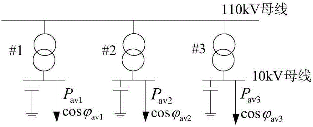
[0032] A 110kV substation consists of 3 transformers of SFZ7-40000 / 110. The schematic diagram is as follows figure 2 Shown.

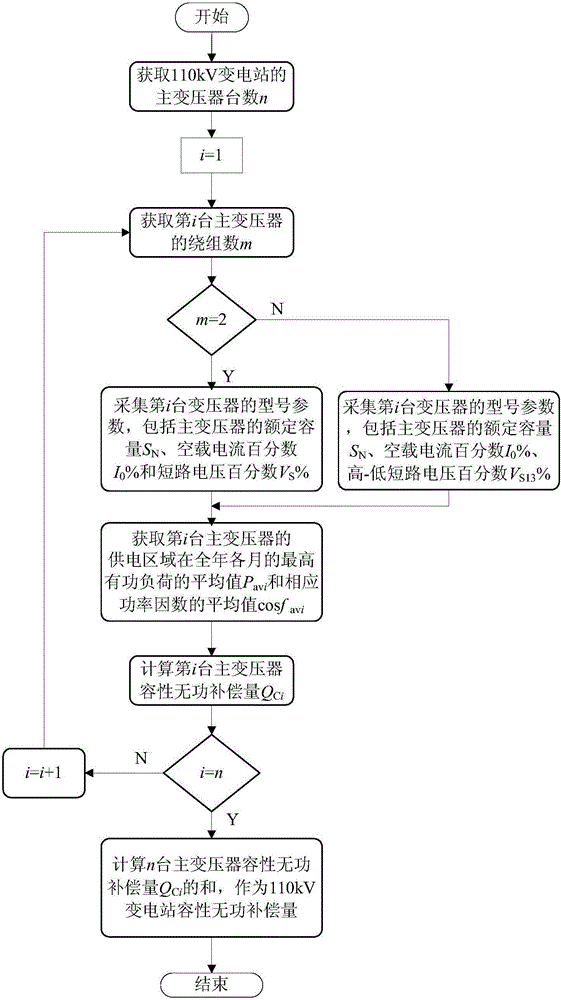
[0033] Combine figure 1 The planning process, a method for configuring the capacitive reactive power compensation capacity of a 110kV substation in a saturated load area, includes the following steps:

[0034] (1) Obtain the number n of main transformers in the 110kV substation, and set i=1: in this embodiment, n=3;

[0035] (2) Obtain the number m of windings of the i-th main transformer: in this embodiment, m is all equal to 2;

[0036] (3) Judge whether m is equal to 2, if yes, collect the model parameters of the i-th main transformer, t...


PUM


Abstract

The invention discloses a capacitive reactive compensation configuration method for an 110kV transformer substation in a saturated load region. The method specifically comprises the following steps: (1) acquiring the main transformer number n of the 110kV transformer substation, wherein i is equal to 1-n; (2) collecting the model parameters of each main transformer, wherein the model parameters comprise rated capacity SN, no-load current percentage I0% and short-circuit voltage percentage VS%; (3) acquiring the highest active load average value Pav and the power factor average value cosphiav of each main transformer in a power supply region in each month all the year; (4) calculating the capacitive reactive compensation QCi of each main transformer and calculating the sum of QCi of n transformers as the capacitive reactive compensation of the 110kV transformer substation. The method disclosed by the invention is suitable for planning the capacitive reactive compensation of the existing 110kV transformer substation in the saturated load region, therefore, local reactive power balancing is facilitated and a lot of reactive-load compensation equipment is prevented from being idled.

Description

Technical field [0001] The invention relates to the technical field of reactive power compensation of substations, and particularly relates to a method for configuring capacitive reactive power compensation capacity of 110kV substations in a saturated load region. Background technique [0002] my country Southern Power Grid's voltage quality and reactive power management standards require that the reactive power configuration of the power system should be able to ensure the reactive power balance of the hierarchical divisions under the system's active load peak and load trough operation mode. The capacitive reactive power compensation of 110kV substation is mainly based on compensating the reactive power loss of the transformer, and appropriately takes into account the reactive power compensation on the load side. The capacitive reactive power compensation configuration is configured according to 10% to 30% of the main transformer capacity. [0003] Configuring reactive power compe...

Claims


Application Information

Patent Timeline
Patent Type & Authority Patents(China)
IPC IPC(8): H02J3/18
CPCY02E40/30
Inventor 张勇军陈艳黄向敏
Owner SOUTH CHINA UNIV OF TECH
Why Eureka
Try Eureka