220 kv transformer station binding type reactive compensation capacity configuration method

A technology of compensation capacity and configuration method, applied in reactive power compensation, reactive power adjustment/elimination/compensation and other directions, which can solve the problems of insufficient substation compensation and excessive substation compensation.

Active Publication Date: 2015-12-23
GRID POWER PLANNING & RES CENT OF GUANGDONG GRID POWER CO LTD +1
View PDF4 Cites 5 Cited by
  • Summary
  • Abstract
  • Description
  • Claims
  • Application Information

AI Technical Summary

Problems solved by technology

[0004] Configuring reactive power compensation according to this principle has the advantages of simplicity, convenience, and strong operability. However, this principle does not make a more optimal configuration according to th

Method used


Image

  • 220 kv transformer station binding type reactive compensation capacity configuration method
  • 220 kv transformer station binding type reactive compensation capacity configuration method
  • 220 kv transformer station binding type reactive compensation capacity configuration method

Examples


Example Embodiment

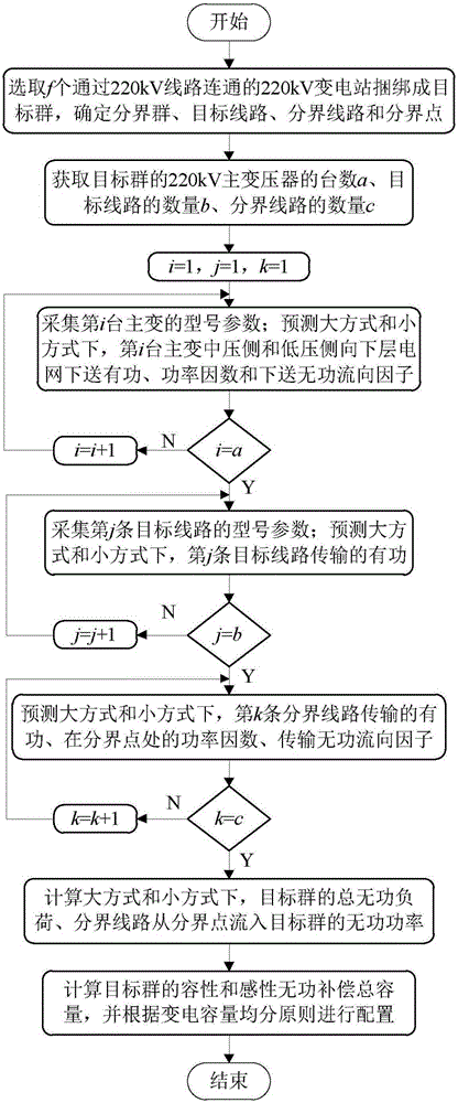
[0046] like figure 1 As shown, the 220kV substation bundled reactive power compensation capacity configuration method includes the following steps:

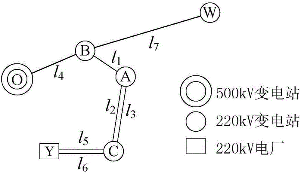
[0047] (1) select f 220kV substations connected by 220kV lines to be bundled into target groups, and 500kV substations, 220kV power plants and 220kV substations connected to target groups by 220kV lines are used as boundary groups: in this embodiment, f=3, and the target group is figure 2 A, B and C substations, the boundary group is figure 2 500kV substation O station, 220kV power plant Y station and 220kV substation W station;

[0048] The 220kV circuit that plays a connected role is as the target line, and the line connecting the boundary group and the target group in the target line is as the boundary line, and the boundary point of each boundary line is set as the endpoint of the line on this side of the boundary group: in this embodiment, target line figure 2 the l 1 , l 2 , l 3 , l 4 , l 5 , l 6 and l 7 , the de...


PUM


Abstract

The invention discloses a 220 kV transformer station binding type reactive compensation capacity configuration method, comprising selecting f 220 kV transformer stations which are communicated through 220 kV circuits to bind the transformer stations to a target group, determining boundary groups, a target circuit, boundary circuits, and boundary points, acquiring parameters of a main transformer and circuit models; then, predicting active power sent by a target group main transformer, power factors, and reactive flow direction factors under a large method and a small method, and active power transmitted by a target circuit, active power transmitted by the boundary circuits, power factors on the boundary points, and transmitted reactive flow direction factors; then, calculating total reactive load of the target group, and reactive power of the boundary circuits flowing from the boundary points to the target group; and finally, calculating inductive and capacitive reactive compensation total capacity of the target group, and according to a power transformation capacity equipartition principle, performing configuration. The method is suitable to be used for reactive compensation planning of 220 kV transformer stations, and is beneficial for balance near reactive layering and divided sections and preventing blindness of reactive configuration.

Description

technical field [0001] The invention relates to reactive power compensation planning of a substation, in particular to a capacitive and inductive reactive power compensation capacity configuration method of a 220kV substation. Background technique [0002] The voltage quality and reactive power management standards of my country's Southern Power Grid require that the reactive power configuration of the power system should be able to ensure the reactive power balance of the stratified and partitioned systems under the operating mode of active load peak and load trough. [0003] The capacitive reactive power compensation of the 220kV substation is mainly to compensate the reactive power loss of the main transformer, and appropriately compensate the reactive power loss of some lines. The compensation capacity is configured according to 10% to 30% of the main transformer capacity, and when the maximum load of the 220kV main transformer is met, the power factor of the high-voltag...

Claims


Application Information

Patent Timeline
IPC IPC(8): H02J3/18
CPCY02E40/30
Inventor 覃芸左郑敏黄春艳何奉禄林勇郑秀波樊扬谢燕燕
Owner GRID POWER PLANNING & RES CENT OF GUANGDONG GRID POWER CO LTD
Why Eureka
Try Eureka