Portable solar panel system and method

A technology for solar panels and drive systems, applied in the field of photovoltaic solar panel deployment systems, can solve problems such as reducing reliability, increasing maintenance requirements, and increasing the cost and complexity of supporting structures for solar panels

Inactive Publication Date: 2015-07-22
封爱国
View PDF8 Cites 5 Cited by
  • Summary
  • Abstract
  • Description
  • Claims
  • Application Information

AI Technical Summary

Problems solved by technology

Each of these moving parts increases the cost and complexity of the solar panel's support structure, while also increasing maintenance requirements and reducing reliability
Furthermore, typical tracking control systems require high power and expensive electronics to move the position and orientation of solar panels for maximum electrical power output

Method used


Image

  • Portable solar panel system and method
  • Portable solar panel system and method
  • Portable solar panel system and method

Examples


Embodiment Construction

[0034] Several exemplary embodiments of simplified portable solar panel systems and methods capable of tracking the sun will now be described. It will be apparent to those skilled in the art that the present invention may be practiced without some or all of the specific details described herein.

[0035] Solar power systems are expected to provide low cost, low maintenance, low operating cost power consumption and long service life. The actual power generated by the solar power system is offset in part by the material, labor and energy expenses required to manufacture, deploy and operate the solar power system. Both capital and labor costs include expenses for manufacturing the photovoltaic array (solar panel), delivery, installation labor hours, installation structure, and long-term operation and maintenance. The system described herein addresses these expenses by providing a simplified, modular, and more portable solar panel system.

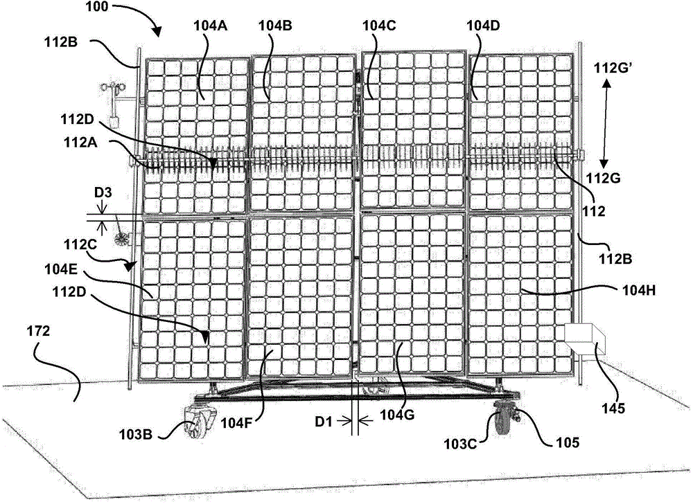
[0036] Figure 1A is a front view of a...


PUM


Abstract

A portable solar panel system and method includes a support structure, one or more solar panels mounted on the support structure, at least three wheels coupled to the support structure and rotatably supporting the support structure on a surface, a controller, a sunlight monitor coupled to the controller and a tracking drive system coupled to the controller and mechanically linked to at least one of the at least three wheels.

Description

technical field [0001] The present invention relates generally to photovoltaic solar panel deployment systems and methods, and more particularly, to systems and methods for deploying portable photovoltaic power generation systems, and solar panel tracking systems. Background technique [0002] Typical photovoltaic solar cell array (solar panel) deployment systems and methods and solar panel tracking systems and methods are very complex, expensive, and require excessive time and materials to complete. Thus, typical solar panel deployment systems and methods consume a significant amount of energy that could be generated over the lifetime of the solar panel system. For example, typical solar panel deployment systems and methods rely on large steel structures to support the solar panels. A large steel structure requires a lot of labor and material to install, and requires a concrete foundation to support the steel structure, as well as many other preparatory works. In another ...

Claims


Application Information

Patent Timeline
Patent Type & Authority Applications(China)
IPC IPC(8): H02S20/32F24S50/20
CPCH01L31/0522H02S20/00F24S30/20F24S30/452F24S50/20F24S2030/133F24S2030/134H02S20/32Y02E10/47Y02E10/50
Inventor 封爱国
Owner 封爱国
Why Eureka
Try Eureka