A Tracking System for Point Targets on Satellite

A trajectory tracking and point target technology, applied in the direction of using feedback control, etc., can solve the problems of uploading communication pressure, positioning accuracy limit side swing positioning accuracy, etc., achieve the effect of simple control method, reduce storage pressure, and improve tracking accuracy

Active Publication Date: 2017-08-29
BEIJING RES INST OF SPATIAL MECHANICAL & ELECTRICAL TECH
View PDF4 Cites 0 Cited by
  • Summary
  • Abstract
  • Description
  • Claims
  • Application Information

AI Technical Summary

Problems solved by technology

There are two traditional point target trajectory tracking systems and methods on the satellite. One is that the ground measurement and control system uploads all position information of the point target trajectory to the satellite. All positions of the target are tracked one by one. This system or method relies on the side swing of the satellite, and its positioning accuracy is also limited by the side swing positioning accuracy of the satellite. To complete the track tracking of the point target, a large amount of position information needs to be uploaded, resulting in upload communication pressure; Another method is that the ground measurement and control system uploads the instructions of each position of the pre-stored point target trajectory to the satellite, and the satellite sends these instructions to the camera one by one in time sequence, and the camera realizes the continuous tracking of the point target trajectory according to the sequence of received instructions. This system or method also needs to upload a large amount of instruction data, causing pressure on traditional communication

Method used


Image

  • A Tracking System for Point Targets on Satellite
  • A Tracking System for Point Targets on Satellite
  • A Tracking System for Point Targets on Satellite

Examples


Embodiment Construction

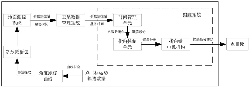
[0019] The present invention proposes a point target trajectory tracking system that can be used in a remote sensing camera. It does not need to go through the side swing of the satellite to realize the capture of the point target by the remote sensing camera, and does not need to upload multiple commands from the satellite to realize the tracking of the point target. , autonomously track and image the point target whose trajectory is predicted by the remote sensing camera. The tracking system of the present invention tracks the moving point target by receiving the parameter data packet of the predicted point target motion trajectory, so that the remote sensing camera can automatically track and image the point target, such as figure 1 It includes a time management unit, a pointing control unit, and a pointing mirror motor mechanism (for realizing the adjustment of the visual axis of the remote sensing camera).

[0020] Before the tracking system of the present invention works...


PUM


Abstract

A trajectory tracking system for a point target on a satellite includes a time management unit, a direction control unit and a directing mirror motor mechanism. A ground measurement and control system sends a data packet containing a curvilinear equation multinomial coefficient and starting and finishing time of curve tracking to the time management unit; the time management unit forwards the data packet to the direction control unit, and the direction control unit is controlled to begin to start tracking control calculation; after receiving the data packet and calculating the angles of a pitching direction and a rolling direction of a directing mirror motor, the direction control unit controls the directing mirror motor mechanism; and the directing mirror motor mechanism controls the direction of a directing mirror to adjust an optical axis of a remote sensing camera according to the angles of the pitching direction and the rolling direction. The trajectory tracking system for the point target on the satellite prevents a plurality of angle tracking instructions from being continuously uploaded to the remote sensing camera, and can control the remote sensing camera to complete continuous tracking of the motion trail of the point target only by transmitting time parameters and multinomial coefficient data in the form of a data packet, the communication efficiency is high, and storage pressure of the tracking system is reduced.

Description

technical field [0001] The invention relates to the technical field of optical imaging and remote sensors, in particular to a point target track tracking system on a star. Background technique [0002] The space-borne remote sensing camera uses push-broom or staring methods to image the scene target or track and image the predicted point target when flying with the satellite. There are two traditional point target trajectory tracking systems and methods on the satellite. One is that the ground measurement and control system uploads all position information of the point target trajectory to the satellite. All positions of the target are tracked one by one. This system or method relies on the side swing of the satellite, and its positioning accuracy is also limited by the side swing positioning accuracy of the satellite. To complete the track tracking of the point target, a large amount of position information needs to be uploaded, resulting in upload communication pressure; ...

Claims


Application Information

Patent Timeline
Patent Type & Authority Patents(China)
IPC IPC(8): G05D3/12
Inventor 付智红刘冰康建兵彭宏刚周峰
Owner BEIJING RES INST OF SPATIAL MECHANICAL & ELECTRICAL TECH
Why Eureka
Try Eureka