High-lift system for aircraft

A lift and aircraft technology, applied in the direction of aircraft power transmission, aircraft power plant, aircraft parts, etc., can solve problems such as restoration, affecting aircraft dispatch rate, and reducing system availability

Active Publication Date: 2020-06-23
COMAC +1
View PDF9 Cites 8 Cited by
  • Summary
  • Abstract
  • Description
  • Claims
  • Application Information

AI Technical Summary

Problems solved by technology

[0009] However, because the mechanical system and the sensor itself must have errors in mechanical and electrical characteristics, the sensor cannot fully restore the pilot's mechanical manipulation into an electrical signal, which will have a certain impact on the control accuracy.
Seriously, the large signal error of a single sensor and the tracking error between multiple sensors will cause the slat channel SLAT1, SLAT2 or flap channel FLAP1, FLAP2 of the high-lift system 3 to half speed, reducing the availability of the system, thereby affecting Aircraft dispatch rate

Method used


Image

  • High-lift system for aircraft
  • High-lift system for aircraft
  • High-lift system for aircraft

Examples


specific example

[0083] The high-lift system 300 of the present invention can be realized through the following two examples, for example.

example 1

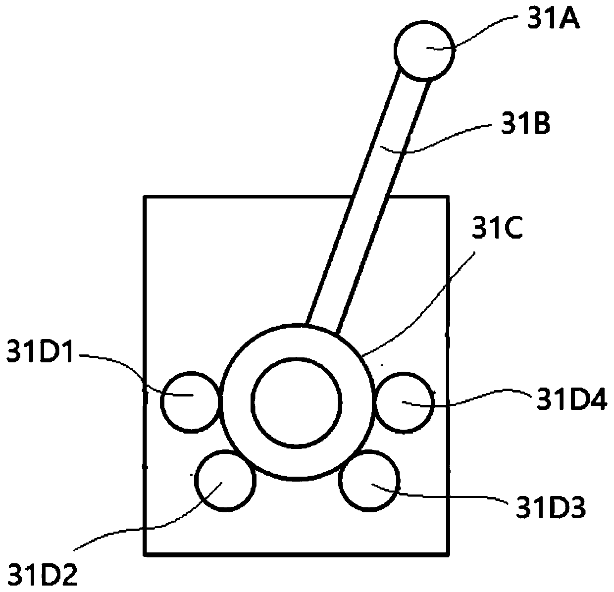
[0085] In the high-lift system, the slat control handle has five positions of 0, 1, 2, 3 and FULL, and the nominal value and tolerance of the signal of the rotary variable differential transformer sensor corresponding to the five positions are -30 ±2 degrees, -15±2 degrees, 0±1 degrees, 15±2 degrees and 30±2 degrees.

[0086] The 5 channels (SLAT1, FLAP1, SLAT2, FLAP2 and BAK) inside the high-lift system are all working normally. The power configuration of the high-lift system is as follows: Figure 8 As shown, the alternating current powered by the generator is converted into direct current, and is supplied to the flap channel FLAP1 and the slat channel SLAT1 of the slat electronic control unit 320A1 through the common 28V DC bus bar of the aircraft, and the ram air turbine generates power The alternating current generated at the time is converted into direct current, and is supplied to the flap channel FLAP2, the slat channel SLAT2 and the backup channel BAK of the sla...

example 2

[0095] Figure 9 A circuit schematic diagram of a high-lift system 3000 with another form of computer (flap electronic control unit) is shown. Here, only the differences from the high-lift system 300 of Example 1 will be described, and the description of the same configuration and electrical connection will be omitted.

[0096] Figure 9 Each of the computers 3200A1, 3200A2 (also known as Flap Electronic Control Units (FECUs)) of this version of the high-lift system 3000 shown is primarily composed of two hardware dissimilar CCMs (Constant Code Modulation) 3210A1a, 3210A1b ( 3210A2a, 3210A2b) and an ACM (Adaptive Coding Modulation) 3220A1c. One CCM (also called control CCM) performs control functions (control channels COM1, COM2), and the other CCM (also called monitoring CCM) performs monitoring functions (monitor channels MON1, MON2). The two CCMs calculate system commands at the same time. After the two CCM commands are consistent, the CCM that executes the control...


PUM


Abstract

The invention discloses a high-lift system for an aircraft. With the high-lift system for the aircraft adopted, the mechanical control of a pilot can be accurately acquired, an effective system instruction can be selected, and the usability of a system can be improved. The high-lift system for the aircraft comprises two dual-channel computers and a single-channel computer; a control handle is provided with rotary variable differential pressure transducers, wherein the number of the rotary variable differential pressure transducers is the same as that of five channels in the high-lift system for the aircraft. Each of the five channels exchanges the signals and signal instructions of the corresponding rotary variable differential transformer sensor with each other in the same time sequence.And after a certain number of system instructions are received in a certain channel, namely a to-be-voted channel, effective system instructions are selected in the to-be-voted channel through a voting mechanism, and are sent to a motor of a power driving unit corresponding to the to-be-voted channel.

Description

technical field [0001] The invention relates to an aircraft high-lift system, and more particularly relates to an aircraft high-lift system using a single-channel computer that generates instructions through a voting mechanism. Background technique [0002] like figure 1 As shown, a modern large aircraft 1 is provided with a slat 12 at the leading edge of the wing and a flap 13 at the trailing edge of the wing on the left and right wings 11 located on both sides of the main body 10 of the aircraft. The slat 12 and the flap 13 transmit the power from the gear boxes 22, 23 corresponding to the slat 12 and the flap 13 in the power drive device 20, and through respective kinematic mechanisms (the slat kinematic mechanism 12A and the flap motion Mechanism 13A) performs extension and / or swivel movements, respectively. [0003] In addition, the flaps 13 of the left and right wings 11 respectively have an inner flap 13a on the side of the aircraft main body 10 and an outer flap 13...

Claims


Application Information

Patent Timeline
IPC IPC(8): B64C13/04B64C13/50
CPCB64C13/50B64C13/0425
Inventor 王伟达陈勇杨志丹王晓熠房峰刘锦涛
Owner COMAC
Why Eureka
Try Eureka