Permanent magnetic speed regulator

A permanent magnet speed governor and permanent magnet rotor technology, applied in electrical components, electromechanical devices, electromechanical transmission devices, etc., can solve the problems of inconvenient installation of permanent magnet speed governors, heat generation, short bearing life, and low utilization of magnetic lines of force. , to achieve the effect of small size, large transmission torque and wide use

Inactive Publication Date: 2015-08-19
GUANGXI CHUANJIAN IND TECH CO LTD
View PDF6 Cites 3 Cited by
  • Summary
  • Abstract
  • Description
  • Claims
  • Application Information

AI Technical Summary

Problems solved by technology

[0003] The invention provides a permanent magnet governor which can solve the problems of the existing permanent magnet governor, such as low utilization of magnetic lines of force, inconvenient installation of the permanent magnet governor, heat generation and short service life of bearings, etc.

Method used


Image

  • Permanent magnetic speed regulator
  • Permanent magnetic speed regulator
  • Permanent magnetic speed regulator

Examples


Embodiment Construction

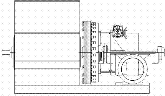
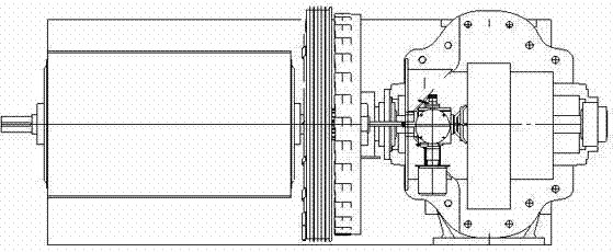
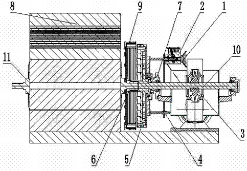
[0023] Such as figure 1 , 2 , 3, and 4, the conductor rotor and the permanent magnet rotor are respectively connected to the input shaft 11 and the output shaft 10, the input shaft is connected to the motor 8, the output shaft 10 is connected to the water pump 10, the conductor rotor is provided with a cylindrical conductor rotor 9, and the permanent magnet rotor is provided with There is a cylindrical permanent magnet rotor 5, and the conductive rotor is provided with a cylindrical conductive rotor 9, which is a double-layer cylindrical shape coaxially arranged with different radii composed of the first layer of cylindrical shape 9-1 and the second layer of cylindrical shape 9-2, The axial lengths of the double-layer cylindrical conductor rotors 9 are equal, and the cylindrical permanent magnet rotor 5 is located between the double-layer cylindrical conductive rotors, which are separated by an air gap. The conductor rotor has double-layer cooling fins and is manufactured wit...


PUM


Abstract

Provided is a permanent magnetic speed regulator, comprising a conductor rotor and a permanent magnetic rotor. The conductor rotor and the permanent magnetic rotor are respectively connected with an input shaft and an output shaft. The conductor rotor is provided with cylindrical conductor rotors. The permanent magnetic rotor is provided with a cylindrical permanent magnetic rotor. The cylindrical conductor rotor arranged on the conductor rotor is in a double layer cylindrical shape. The cylindrical permanent magnetic rotor is between the cylindrical conductor rotors in the double layer cylindrical shape. The permanent magnetic speed regulator is advantaged in that meshing area between the cylindrical conductor rotors and the cylindrical permanent magnetic rotor is effectively increased, and objectives of small volume and large transmission torque are realized, axial movement of a permanent magnet between the double layer cylindrical conductor rotors is adjusted to change meshing area, so as to realize speed regulation, fan blades are used to radiate heat, volume of the permanent magnetic speed regulator can be made smaller, the radius where magnetic force is in can be changed according to power requirement, the permanent magnetic speed regulator can be installed by just changing a coupling without moving a motor, the permanent magnetic speed regulator can be used directly, and use is convenient, and purposes are wider.

Description

technical field [0001] The invention relates to a speed regulating mechanism between a prime mover and a load, in particular to a permanent magnet speed regulator which fully utilizes the magnetic force line of a permanent magnet, which can save energy during adjustment. Background technique [0002] At present, the known permanent magnet speed governors are disc-shaped and single-tube shaped, and the utilization rate of the magnetic force lines of the permanent magnets is not high, and the prime mover or load must be displaced to install the permanent magnet speed governor. Ordinary permanent magnet speed governors do not dissipate heat well when they are hot, and there is a clearance fit between dynamic and static friction in the bearing housing, resulting in poor lubrication of the bearings and short service life. Contents of the invention [0003] The invention provides a permanent magnet governor which can solve the problems of low utilization of magnetic force lines ...

Claims


Application Information

Patent Timeline
Patent Type & Authority Applications(China)
IPC IPC(8): H02K51/00
Inventor 李传建
Owner GUANGXI CHUANJIAN IND TECH CO LTD
Why Eureka
Try Eureka