Meshing type pipe pile quick coupling structure

A kind of joint structure and fast technology, which can be used in infrastructure engineering, sheet pile walls, buildings, etc., and can solve problems such as inaccurate alignment of connecting pins and connecting grooves, rotten ends of pipe pile joints, and reduced bearing capacity of pipe piles. , to shorten the construction time, prevent damage, and increase the meshing area.

Pending Publication Date: 2019-07-16
QINGDAO TECHNOLOGICAL UNIVERSITY
View PDF15 Cites 1 Cited by
  • Summary
  • Abstract
  • Description
  • Claims
  • Application Information

AI Technical Summary

Problems solved by technology

The meshing mechanical quick joint technology can not only transmit pressure reliably, but also withstand the effects of bending moment, torque, shearing force and tensile force, but it requires too many connecting pins, bolt holes, and connecting grooves. When connecting, there is a high requirement for the butt joint of the connecting pin and the connecting groove. Under actual conditions, due to the manufacturing error of the material or the artificial groove does not meet the requirements, some connecting pins and the connecting groove will be inaccurate, resulting in the connection pin and the connecting groove. The damage of the notch will further cause the eccentric damage of the pile body during the pile sinking, resulting in the joint of the pipe pile being squeezed and cracked after the drop hammer construction, resulting in the rotten head of the pipe pile, which seriously reduces the bearing capacity of the pipe pile

Method used


Image

  • Meshing type pipe pile quick coupling structure
  • Meshing type pipe pile quick coupling structure
  • Meshing type pipe pile quick coupling structure

Examples


Embodiment 1

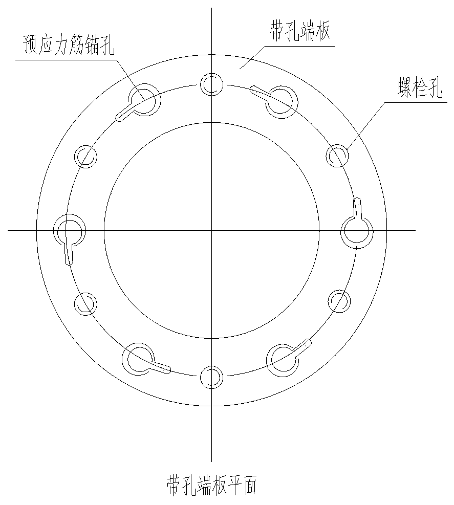
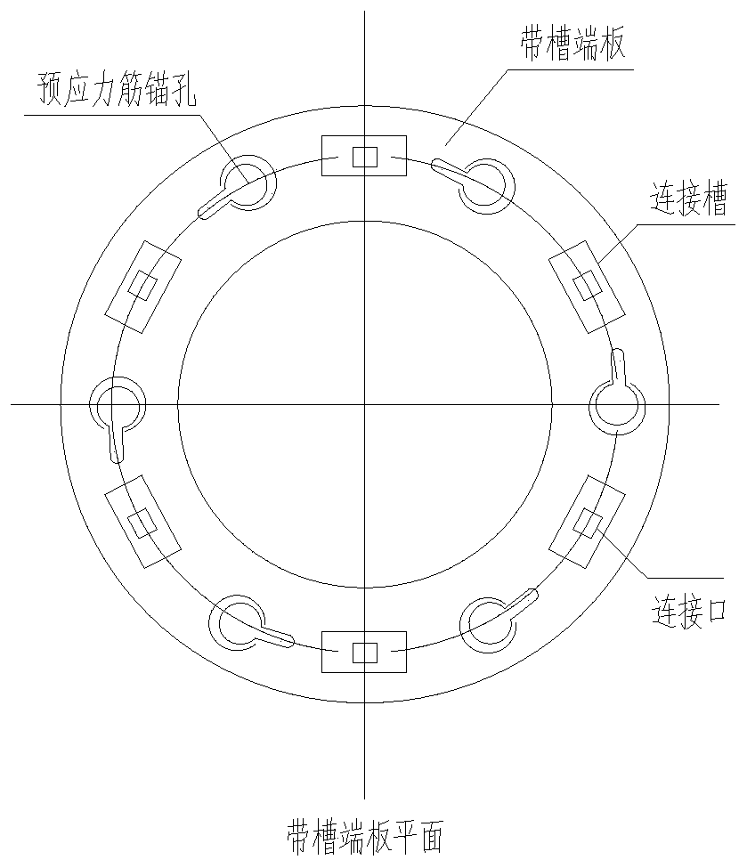
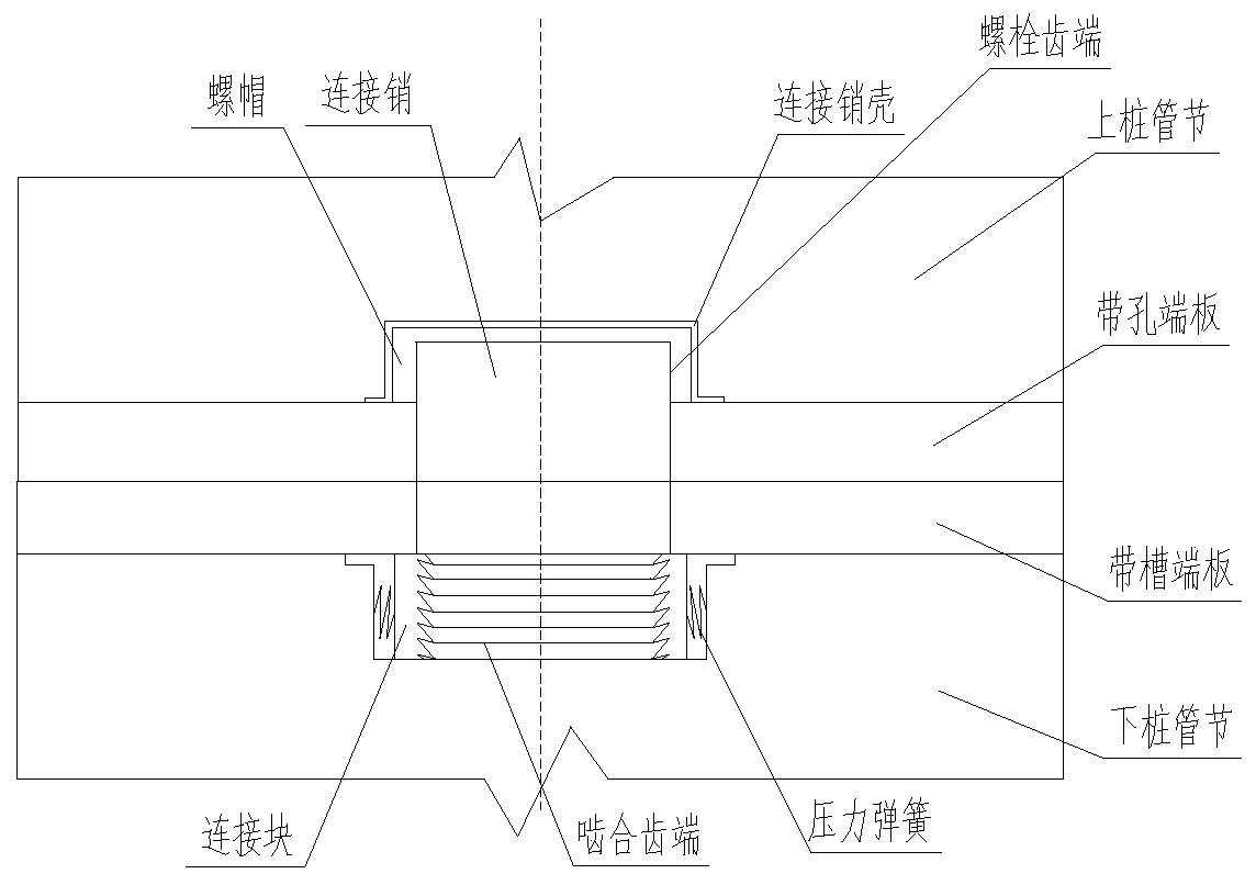
[0027]The main structure of the meshing pipe pile quick joint structure involved in this embodiment includes an upper section pipe pile 1, an upper end plate 2, a lower section pipe pile 3, a lower end plate 4, bolt holes 5, a connecting groove 6, a connecting port 7, a prestressed Rib anchor hole 8, connecting pin 9, lower meshing tooth 12, nut 13, connecting block 14, upper meshing tooth 15 and pressure spring 16; the bottom of the upper segment pipe pile 1 is provided with an upper end plate 2 of circular structure, and the lower The top of the joint pipe pile 3 is provided with a lower end plate 4 of circular structure, the upper end plate 2 is provided with four bolt holes 5 of circular structure at equal intervals, and the lower end plate 4 is provided with four rectangular structure bolt holes at equal intervals. The connection groove 6, the center of the connection groove 6 is provided with a cross-shaped connection port 7, the position of the bolt hole 5 corresponds to...


PUM


Abstract

The invention belongs to the technical field of pipe pile joints, and relates to a meshing type pipe pile quick coupling structure. The main body structure comprises an upper-section pipe pile, an upper end plate, a lower-section pipe pile, a lower end plate, bolt holes, connecting grooves, connecting openings, prestressed rib anchoring holes, connecting pins, lower meshing teeth, nuts, connectingblocks, upper meshing teeth and pressure springs. The number of the bolt holes, the connecting grooves and the prestressed rib anchor holes in the upper end plate and the lower end plate is reduced to four, thus the probability of inaccurate alignment of the connecting pins and the connecting grooves is reduced, and the construction operation time is shortened; the lower parts of the connecting pins are changed into a cross-shaped section tooth form from a rectangular tooth form, the lower meshing teeth inclined downwards are arranged on the surfaces of the cross-shaped bodies, and the uppermeshing teeth which are inclined upwards are arranged on the surface of the connecting blocks, so that the lower meshing teeth are easily pressed into the upper meshing teeth and are not easy to pullout; and the self-locking function is achieved, and the reduction of shear resistance and bending-resistant bearing capacity of a joint of the upper-section pipe pile and the lower-section pipe pile due to the reduction of the bolt holes and the connecting grooves is avoided.

Description

[0001] Technical field: [0002] The invention belongs to the technical field of pipe pile joints, and in particular relates to an engaging type pipe pile quick joint structure, which realizes quick pile connection and ensures the shear resistance and bending resistance bearing capacity of pipe piles. [0003] Background technique: [0004] Prestressed concrete pipe piles have the advantages of fast construction speed, high single pile bearing capacity, and good pile quality. They are widely used. There are two types of prestressed concrete pipe piles: pre-tensioned prestressed pipe piles and post-tensioned prestressed pipe piles. : The pretensioning method is to improve the crack resistance of reinforced concrete members and avoid premature cracks in reinforced concrete members, and to pre-stress a concrete member during the prefabrication process to improve the performance of the member, usually before pouring concrete The production method of tensioned steel bars is also cal...

Claims


Application Information

Patent Timeline
Patent Type & Authority Applications(China)
IPC IPC(8): E02D5/52E02D5/58
CPCE02D5/526E02D5/58
Inventor 王玉田张龙姜福香孟令波王迅
Owner QINGDAO TECHNOLOGICAL UNIVERSITY
Why Eureka
Try Eureka