

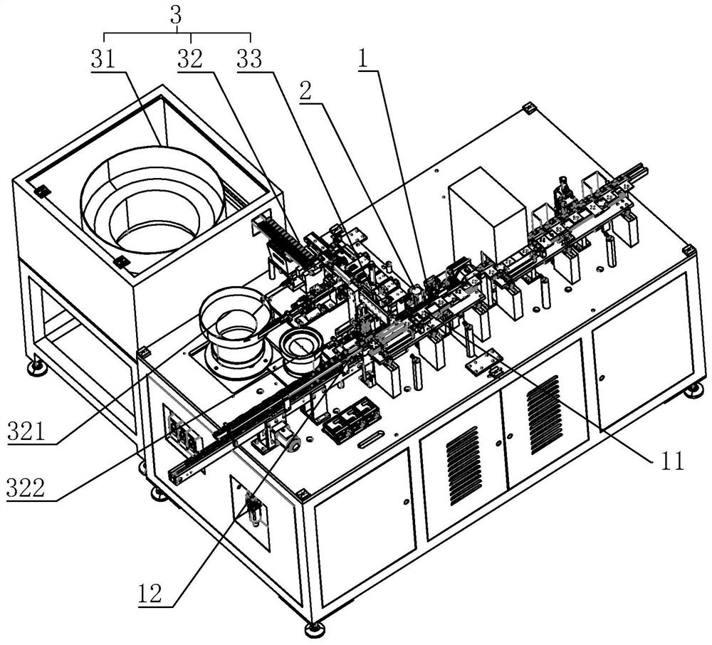
Relay base cover device
A technology for delivering relays and caps, which is applied to relays, circuits, electrical components, etc., can solve the problems of low placement efficiency, easy bias, and lower relay base capping efficiency, so as to increase placement efficiency and reduce the probability of misalignment , high efficiency effect
- Summary
- Abstract
- Description
- Claims
- Application Information
AI Technical Summary
Problems solved by technology
Method used
Image

Examples
Embodiment approach
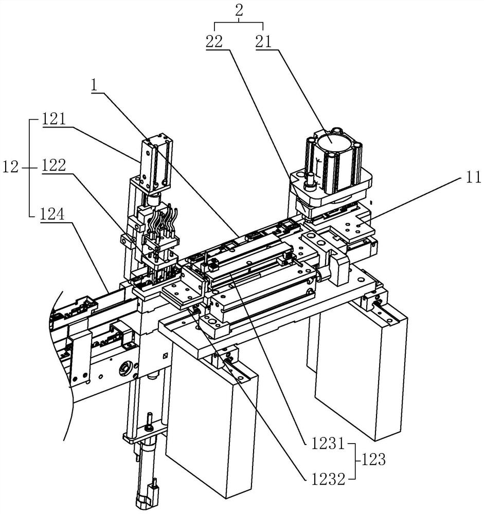
[0028] As an improved specific implementation, the detection and waste discharge mechanism 12 includes a detection cylinder 121, a detection head 122, a waste discharge assembly 123 communicating with the detection head 122, and a waste discharge track 124. One end of the waste discharge track 124 is connected to The ends of the transmission track 1 are connected, the detection cylinder 121 is fixed above the end of the waste discharge track 124 opposite to the transmission track 1, the detection head 122 is fixed on the push rod of the detection cylinder 121, and pushed by the detection cylinder 121, it extends into the Detect the assembled terminals in the casing, and output a signal to the waste discharge assembly 123 when the detection result is unqualified, the waste discharge assembly 123 pushes the current casing into the waste discharge track 124, through the cooperation of the detection head 122 and the detection cylinder 121 function, it can simply and effectively det...
PUM
 Abstract
Description
Claims
Application Information