
Cooling apparatus for a fuel cell powered vehicle

a fuel cell and cooling apparatus technology, applied in the direction of indirect heat exchangers, lighting and heating apparatus, electrochemical generators, etc., can solve the problems of deteriorating radiating performance of the second radiator, difficult to ensure the necessary radiation area, and difficult to keep in the cooling wind, so as to achieve maximum radiation area, improve mounting efficiency of the vehicle, and simplify the structure of the cooling water passage

Inactive Publication Date: 2009-10-29
SUZUKI MOTOR CORP
View PDF2 Cites 17 Cited by
  • Summary
  • Abstract
  • Description
  • Claims
  • Application Information

AI Technical Summary

Benefits of technology

The invention is a cooling system for a fuel cell powered vehicle that includes two separate cooling passages for the fuel cell and other electric equipment. The first cooling passage is located behind the front bumper and is cooled by a cooling wind introduced through an opening in the front bumper. The second cooling passage is made up of two radiators located in the side portions of the vehicle and is cooled by a cooling wind introduced from the front bumper. The second radiators are curved along the inner surface of the front bumper and are connected by a cooling water piping. This design maximizes the radiation area and improves the cooling performance of the second radiators. The cooling water is supplied in one direction, reducing the number of branch and confluent points in the cooling water passage and simplifying the structure. Overall, this cooling system simplifies the vehicle's cooling system and improves its performance.

Problems solved by technology

However, in the case of arranging the second radiator into such a narrow space as mentioned above, there is an inconvenience in that for a radiator having a flat shape, it is difficult to ensure a necessary radiation area.
The second radiator has to be arranged at a position that is away from an opening portion of the front bumper and is difficult to keep in a cooling wind.
Thus radiating performance of the second radiator deteriorates.
As further disclosed in JP-A-2004-168193, in the case where a branch point and a confluent point are provided for a cooling water passage of the second cooling passage and the second radiators are respectively arranged in parallel on the two cooling water passages for communicating the branch point and the confluent point, there is an inconvenience in that a structure of the cooling water passages becomes complicated due to the branch point and the confluent point.
Therefore mounting efficiency to the vehicle deteriorates.
Further, in the case of cooling the second radiators by cooling fans, there is an inconvenience since the temperatures of the cooling water which flow into the two second radiators are almost equal.
Unless the cooling fans are attached to both of the second radiators, it is difficult to remarkably improve the radiating performance.

Method used


Image

  • Cooling apparatus for a fuel cell powered vehicle
  • Cooling apparatus for a fuel cell powered vehicle
  • Cooling apparatus for a fuel cell powered vehicle

Examples


Embodiment Construction

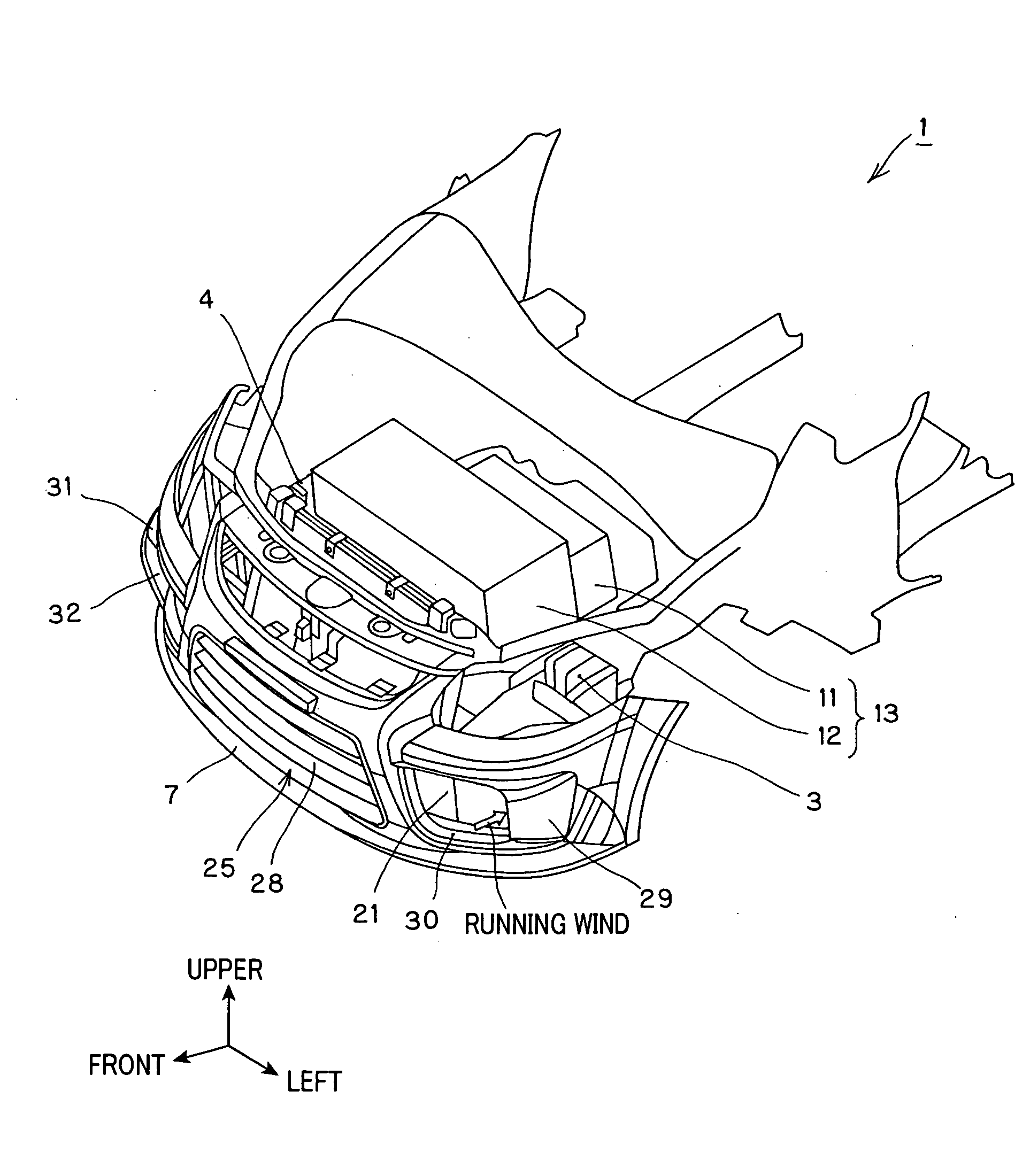
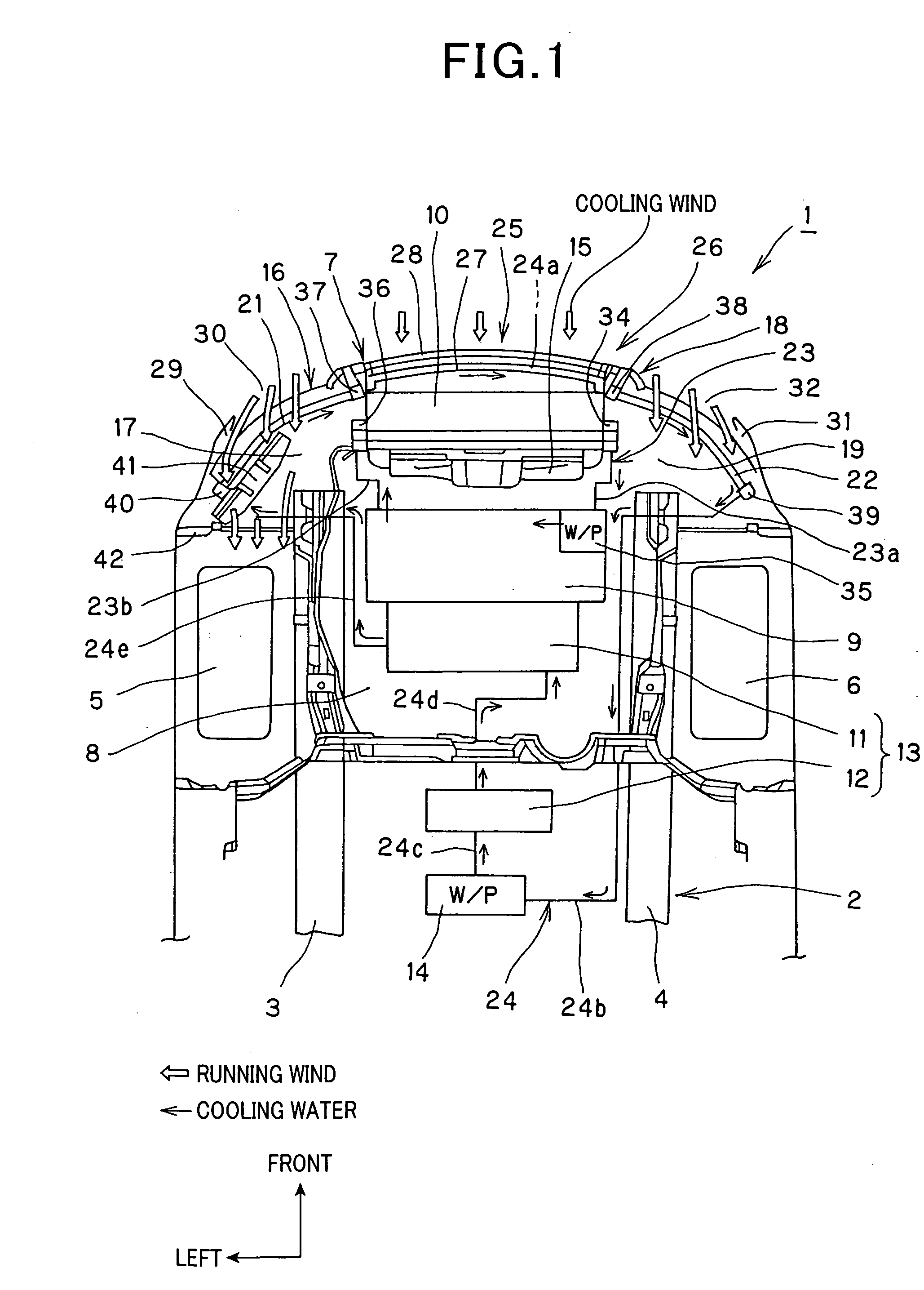
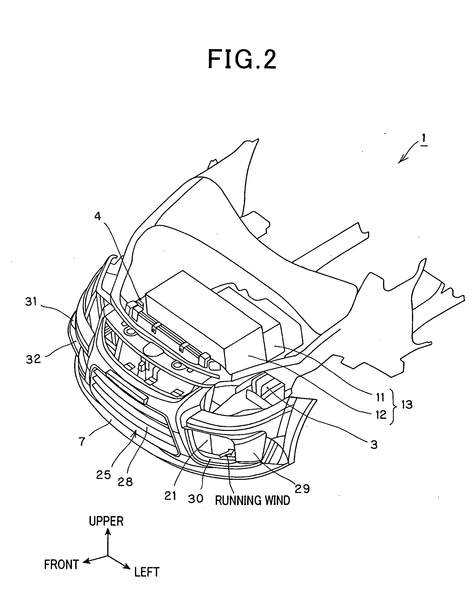
[0021]FIGS. 1 to 4 illustrate an embodiment of the invention. FIGS. 1 to 3 show a fuel cell powered vehicle 1.

[0022]A vehicle body 2 of the fuel cell powered vehicle 1 has a pair of side frames extending in the vehicle front / rear direction as shown in FIGS. 1 to 3, that is, a left-side frame 3 and a right-side frame 4.

[0023]Left and right front wheels 5 and 6 are respectively arranged in outside portions of front portions of the left-side frame 3 and the right-side frame 4. A front bumper 7 is arranged in the front portions of the left-side frame 3 and the right-side frame 4.

[0024]An engine room 8 is formed in the front portion of the fuel cell powered vehicle 1.

[0025]As shown in FIGS. 1 to 3, a fuel cell 9 is mounted in a center portion in the vehicle width direction in the engine room 8 in a laterally mounting state so that a longitudinal direction is oriented transverse to the vehicle width direction. In the front portion of the fuel cell 9, a first radiator 10 is arranged behind...


PUM

PropertyMeasurementUnit
widthaaaaaaaaaa
widthaaaaaaaaaa
electric conductivityaaaaaaaaaa

Abstract

A cooling apparatus for a fuel cell powered vehicle includes a first cooling passage for providing cooling water between a fuel cell and a first radiator and a second cooling passage for providing cooling water between electric apparatuses other than the fuel cell and a second radiator. The first radiator is arranged behind a front bumper and in a center portion in a vehicle width direction, a pair of radiators constructing the second radiator are arranged in side portions in the vehicle width direction from the first radiator and in a space surrounded by curved portions of the front bumper. When the vehicle is viewed from an upper direction, each second radiator is curved along an inner surface of the front bumper, and inner edge portions of the second radiators are coupled by a cooling water piping.

Description

FIELD OF THE INVENTION[0001]The invention relates to a cooling apparatus for a fuel cell powered vehicle and, more particularly, to a cooling apparatus for a fuel cell powered vehicle to improve radiating performance of a radiator arranged in a front portion of the vehicle.BACKGROUND OF THE INVENTION[0002]In fuel cell powered vehicles in the related art, a first cooling passage for cooling a fuel cell main body and a second cooling passage for cooling electric apparatuses such as a motor, an inverter, and the like are independently formed. A main reason why such a construction is used is that a super-low electric conductivity is required for cooling water flowing in the first cooling passage.[0003]As for the fuel cell, its heat generation amount is larger than those of other electric apparatuses and it is necessary that a first radiator arranged in the first cooling passage is set to be larger than a second radiator arranged in the second cooling passage.[0004]In the fuel cell power...

Claims


Application Information

Patent Timeline
Patent Type & Authority Applications(United States)
IPC IPC(8): F28D1/00H01M8/04
CPCF28D2001/0273F28D2021/0043H01M8/04007Y02T90/32H01M2250/20Y02E60/50H01M8/04067Y02T90/40
Inventor FURUTA, TOSHIYUKI
Owner SUZUKI MOTOR CORP
Learn More