High-efficiency surface mounting method and device

A placement machine and placement technology, which is applied in the direction of assembling printed circuits with electrical components, can solve the problems of large structure, low placement efficiency, and large area occupation, and achieve small footprint, improved placement efficiency, and land occupation. change effect

Inactive Publication Date: 2014-12-10
广东田津电子技术有限公司
View PDF5 Cites 16 Cited by
  • Summary
  • Abstract
  • Description
  • Claims
  • Application Information

AI Technical Summary

Problems solved by technology

[0007] There are four technical problems to be solved in the present invention: 1) Overcome the problem that the circuit board of the existing placement machine can only be placed in an absolutely static state, which leads to low placement efficiency; 3) To overcome the shortcomings of the limited placement efficiency improvement caused by the two sets of placement mechanisms of the above-mentioned placement machine adopting a fragmented mode without coordination when placing components; 4) To overcome the problem that the above-mentioned placement machine does not substantially solve the problem of continuous conveying of circuit boards and placement of components on circuit boards of unlimited length continuously conveyed by the placement mechanism

Method used


Image

  • High-efficiency surface mounting method and device
  • High-efficiency surface mounting method and device
  • High-efficiency surface mounting method and device

Examples


Embodiment Construction

[0036] In the following, specific implementations of the high-efficiency placement machine of the present invention will be introduced in conjunction with the accompanying drawings.

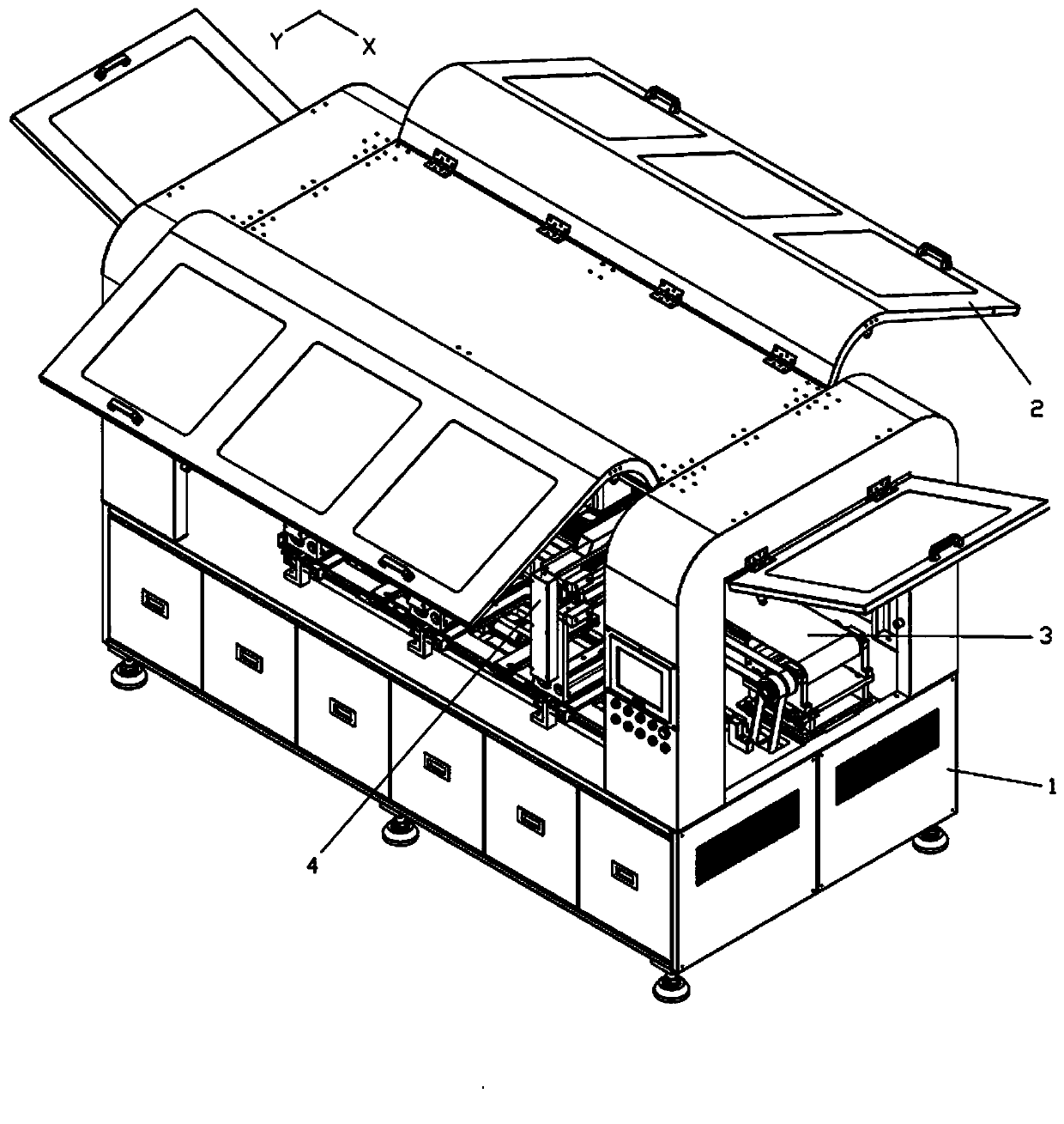
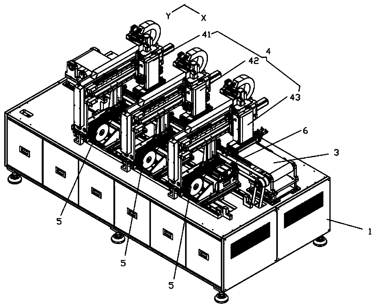
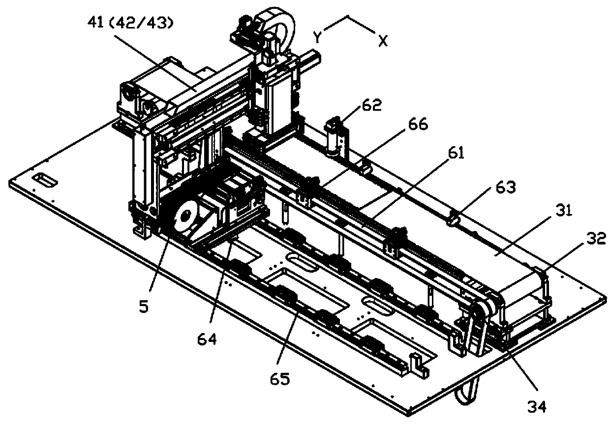
[0037] Such as figure 1 As shown, the high-efficiency placement machine includes a board feeding mechanism 3 for conveying circuit boards along the X direction, and a placement mechanism 4 for at least two groups of mounting components (in this embodiment, the first group of placement mechanisms 41, the second group of placement mechanisms chip mechanism 42 and the third group of chip placement mechanism 43), the conveying component mechanism 5, and the synchronous follower mechanism 6 that the chip placement mechanism and the circuit board run synchronously and at a constant speed when the chip placement mechanism mounts components.

[0038] Such as Figure 4 As shown, each group of patch mechanism 4 includes a moving beam device 44, a lifting slide device 45 and a suction element device 46. Th...


PUM


Abstract

The invention discloses a high-efficiency surface mounting method and device, and relates to the technology of surface mounting of components on printed circuit boards. The high-efficiency surface mounting method includes adopting a board conveying mechanism for conveying circuit boards, adopting a plurality of surface mounting mechanisms to mount the components on the circuit boards, penetrating and inserting surface-mounted components on the same circuit board conveyed by the board conveying mechanism by the surface mounting mechanisms. When mounting the components, the surface mounting mechanism synchronously runs with the circuit boards at constant speed, continuous mounting is realized during constant-speed motion of the circuit boards, the circuit boards are needless of dead time and free of length limit, and the components are mounted on ultralong and rolled circuit boards at high speed. The high-efficiency surface mounting device comprises a board conveying mechanism, a surface mounting mechanism, a component conveying mechanism and a synchronous following mechanism, wherein the synchronous following mechanism enables the surface mounting mechanism and the circuit boards to synchronously run at constant speed when the surface mounting mechanism mounts the component. The problem of continuous surface mounting during constant-speed motion of the circuit boards is solved, the circuit boards are free of length limit, surface mounting is high in efficiency, output is high, and the surface mounting device is small in size and stable and reliable in performance.

Description

technical field [0001] The invention relates to the technology of mounting components such as resistors, capacitors and light-emitting diodes (LED lamp beads) on a printed circuit board, especially a high-efficiency mounting method and a high-efficiency mounting machine. Background technique [0002] With the continuous miniaturization and integration of electronic components, higher and higher requirements are put forward for the technology of mounting electronic components such as resistors, capacitors and light-emitting diodes (LED lamp beads) on printed circuit boards. In the industry, placing electronic components on a printed circuit board is called a patch, and its equipment is called a placement machine. Taking LED as an example, as a new type of light source, LED has the advantages of high brightness, low power consumption, long life, stable performance, and easy matching with integrated circuits. It is being vigorously promoted in landscape lights, background light...

Claims


Application Information

Patent Timeline
Patent Type & Authority Applications(China)
IPC IPC(8): H05K3/30
Inventor 梅晓鸿吴伟斌
Owner 广东田津电子技术有限公司
Why Eureka
Try Eureka