Vertically depressible joint and pressure-cooker provided with one such joint

a vertical depressor and pressure cooker technology, which is applied in the direction of mechanical equipment, refusing gathering, cooking vessels, etc., can solve the problems of generating mechanical resistance to the placement and locking operation, affecting the sealing of the utensil and the safety of the user, and suffering from certain drawbacks, etc., to achieve the effect of improving reliability, simple and robust structure, and being inexpensive to manufactur

Inactive Publication Date: 2015-01-13
SEB SA
View PDF18 Cites 68 Cited by
  • Summary
  • Abstract
  • Description
  • Claims
  • Application Information

AI Technical Summary

Benefits of technology

[0018]Objects assigned to the invention are thus to remedy the above-mentioned drawbacks and to propose a novel sealing gasket for a cooking utensil for cooking food under pressure that, while procuring good sealing of the cooking enclosure, makes it possible to place and to lock the lid on the vessel particularly simply, intuitively, and safely.
[0020]Another object assigned to the invention is to propose a novel sealing gasket that is of simple and robust structure and that is inexpensive to manufacture.
[0021]Another object assigned to the invention is to propose a novel sealing gasket that imparts improved reliability, improved longevity, and improved operating safety to the cooking utensil.
[0022]Another object assigned to the invention is to propose a novel cooking utensil for cooking food under pressure that can be closed in particularly easy, intuitive, and safe manner with very little effort.
[0023]Another object assigned to the invention is to propose a novel cooking utensil for cooking food under pressure that presents good ergonomics and that offers excellent safety guarantees while it is being handled.
[0026]locking means making it possible to hold the lid on the vessel, said locking means comprising at least one first locking member that is secured to or integral with the lid and at least one second locking member that is secured to or integral with the vessel, the first locking member being designed to be engaged under the second locking member, after the lid has been placed on the vessel, in order to hold said lid on said vessel;

Problems solved by technology

Unfortunately, although known gaskets are generally satisfactory, they sometimes suffer from certain drawbacks.
The presence of such gaskets may, in certain cases, hinder placing or locking the lid on the vessel insofar as said gaskets being compressed can generate mechanical resistance to the placement and locking operations.
Unfortunately, such utensil closure with force can expose the gasket, and, to a lesser extent, the locking members, to excessive stresses that can cause them to be degraded by premature wear, or indeed to be deformed, which is naturally detrimental to the sealing of the utensil and to the safety of the user.
In addition, the gasket being compressed and the friction exerted by said gasket against the walls of the vessel or of the lid generates mechanical resistance to the lid being put in place on the vessel, which reduces the comfort of use of the utensil.
Such closure under stress also increases the risk that the user might accidentally tip the utensil over and tip out its contents at the time of closure, in particular if said closure takes place while the utensil is disposed on a narrow or slippery support, such as a work surface or a stovetop.
In addition, the often uneven compression of the gasket during the closure may lead to poor horizontal positioning of the lid relative to the gasket, and therefore to poor operation of the locking members, which sometimes requires the user to make several attempts at putting the lid in place before obtaining satisfactory placement thereof.

Method used


Image

  • Vertically depressible joint and pressure-cooker provided with one such joint
  • Vertically depressible joint and pressure-cooker provided with one such joint
  • Vertically depressible joint and pressure-cooker provided with one such joint

Examples


Embodiment Construction

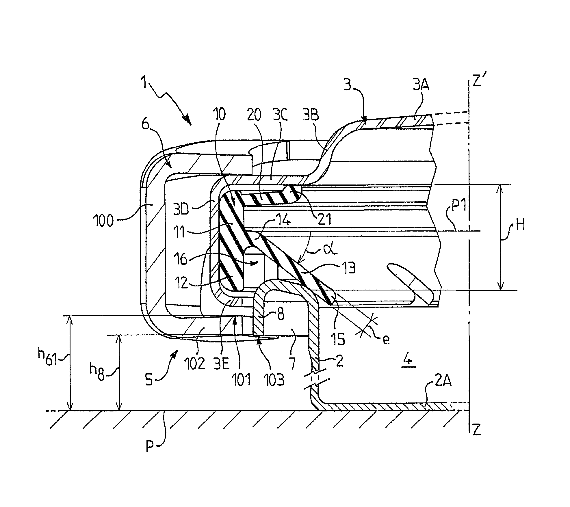
[0037]The present invention relates to a cooking utensil 1 for cooking food under pressure, preferably of the domestic pressure cooker type, said utensil comprising a vessel 2 and a lid 3 that is designed to be mounted on said vessel 2, and more preferably that is designed to be placed on the top rim 7 of said vessel, to define a cooking enclosure 4.

[0038]For convenience of description, it is considered below that the cooking utensil 1 is placed on a work surface P that is plane and horizontal, and that the lid 3 is superposed substantially in register with the vessel 2 along the vertical axis (ZZ′).

[0039]The lid 3 may be provided with a convex and raised central zone 3A that is continued radially outwards, going towards the outside of the lid 3, by a dropped flank 3B, itself followed by an annular flat 3C that is itself continued by a dropped annular edge 3D that is preferably substantially flat and vertical, which annular edge is terminated by an inwardly rolled end segment 3E, as...


PUM


Abstract

Provided is a sealing gasket for a cooking utensil, the utensil includes a vessel and a lid; at least one first locking member and at least one second locking member, the sealing gasket being designed to be interposed between the lid and the vessel and being characterized in that it is designed so that, while the lid is docking with the vessel, said sealing gasket fits over the top rim and comes into contact with said lid and with said vessel while the first locking member is situated at a first height (h61) greater than or equal to the height (h8) at which the second locking member is situated, and is then depressed under the weight of the lid alone to bring the first locking member to a second height (h62) that is less than the height (h8) at which the second locking member is situated.

Description

TECHNICAL FIELD[0001]The present invention relates to the general technical field of utensils for cooking food under pressure in an atmosphere full of steam, such as pressure cookers.[0002]The present invention relates more particularly to sealing gaskets designed to be put in place in such utensils so as to provide sealing between the inside and the outside of the utensil when it is in operation.[0003]The present invention thus relates to a sealing gasket for a cooking utensil for cooking food under pressure, said utensil comprising:[0004]a vessel and a lid that is designed to be mounted on said vessel to define a cooking enclosure;[0005]locking means making it possible to hold the lid on the vessel, said locking means comprising at least one first locking member that is secured to or integral with the lid and at least one second locking member that is secured to or integral with the vessel, the first locking member being designed to be engaged under the second locking member, afte...

Claims


Application Information

Patent Timeline
Patent Type & Authority Patents(United States)
IPC IPC(8): A23B4/052A47J27/08
CPCA47J27/0804A47J27/0806A47J27/08F16J15/06Y10S220/912
Inventor CHAMEROY, ERICCARTIGNY, MICHEL PIERRE
Owner SEB SA
Why Eureka
Try Eureka