Visual-positioning mobile phone accessory attaching system

A visual positioning and placement system technology, applied in packaging, labeling machines, transportation and packaging, etc., can solve the problems of low cost performance, low efficiency, and reduced efficiency, and achieve low cost of line replacement, low production process requirements, and reduced The effect of the failure rate

Active Publication Date: 2016-02-03
DONGGUAN GOSUNM MACHINERY EQUIP CO LTD
View PDF6 Cites 17 Cited by
  • Summary
  • Abstract
  • Description
  • Claims
  • Application Information

AI Technical Summary

Problems solved by technology

[0002] The traditional auxiliary material sticking equipment usually sticks one kind of auxiliary material on one machine, and the stripping and sticking actions are serial, without a vision system or with a simple vision system (the camera follows the mechanical arm, and takes a photo to locate the auxiliary material to be sucked before peeling off the material. ), this type of system has inherent defects. One device can only paste one kind of auxiliary material. Usually, each model of mobile phone case needs to be pasted with multiple auxiliary materials. It needs to purchase multiple such placement machines to complete, and the cost performance is low.
In

Method used


Image

  • Visual-positioning mobile phone accessory attaching system
  • Visual-positioning mobile phone accessory attaching system
  • Visual-positioning mobile phone accessory attaching system

Examples


Embodiment Construction

[0032] The preferred embodiments of the present invention are given below in conjunction with the accompanying drawings to describe the technical solution of the present invention in detail.

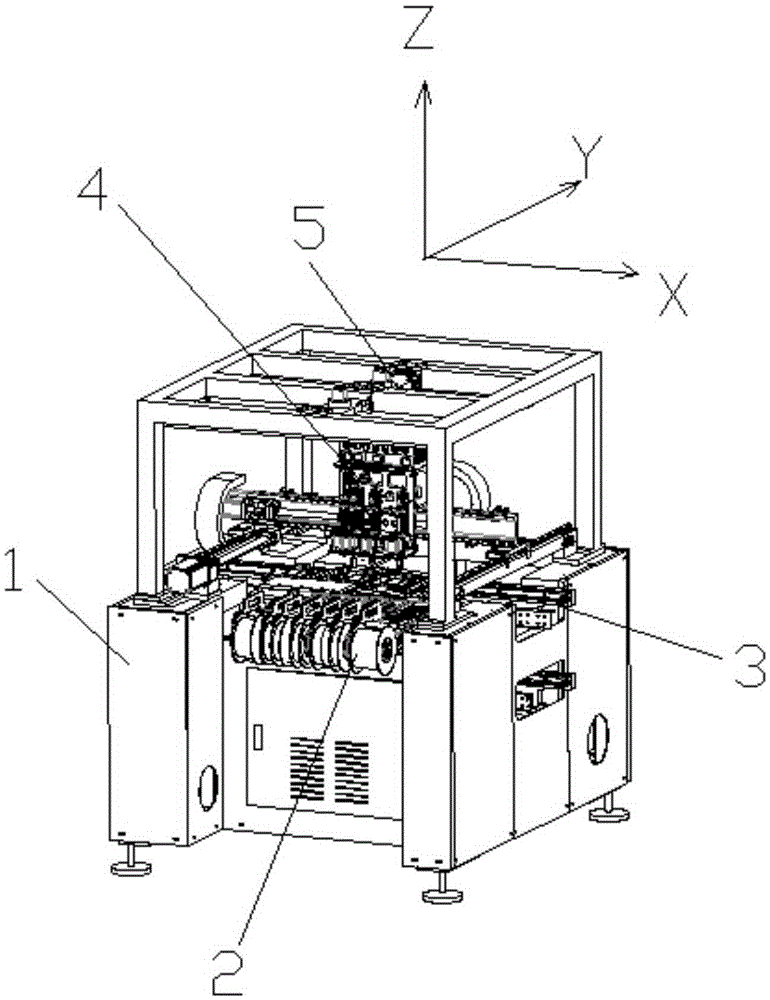
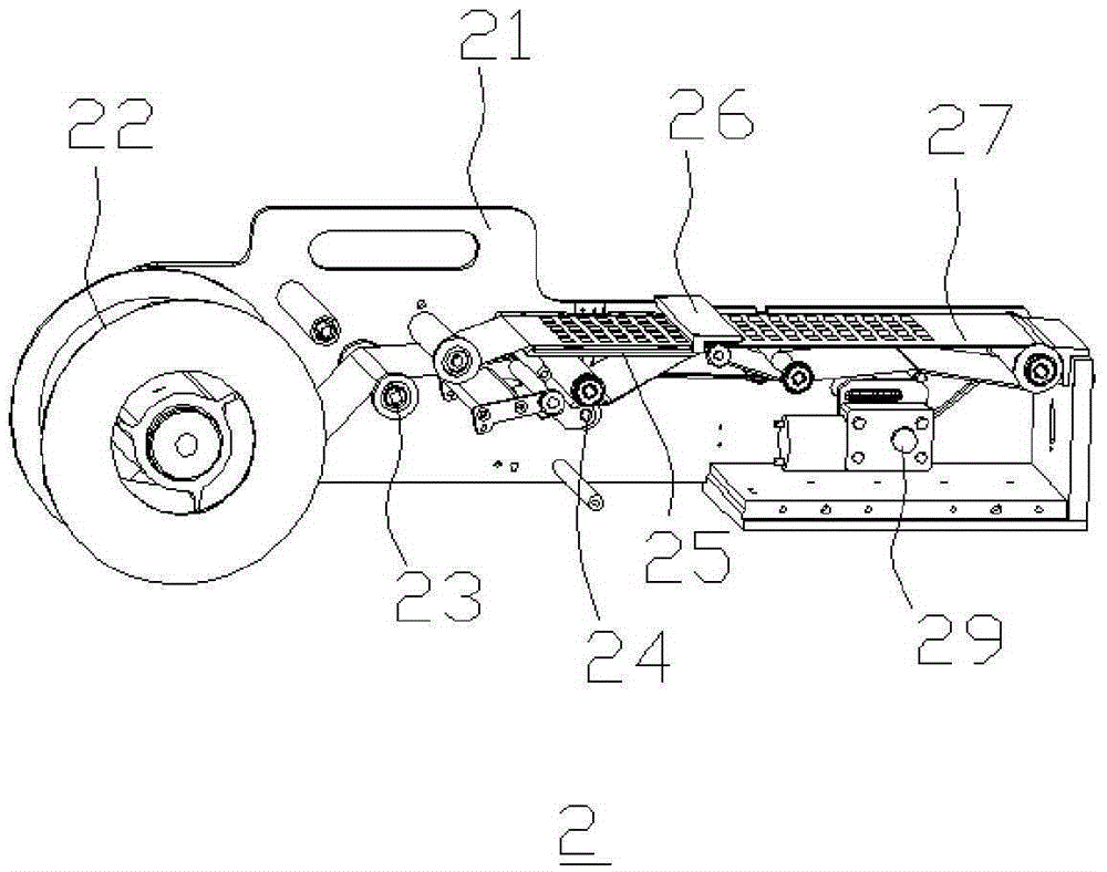
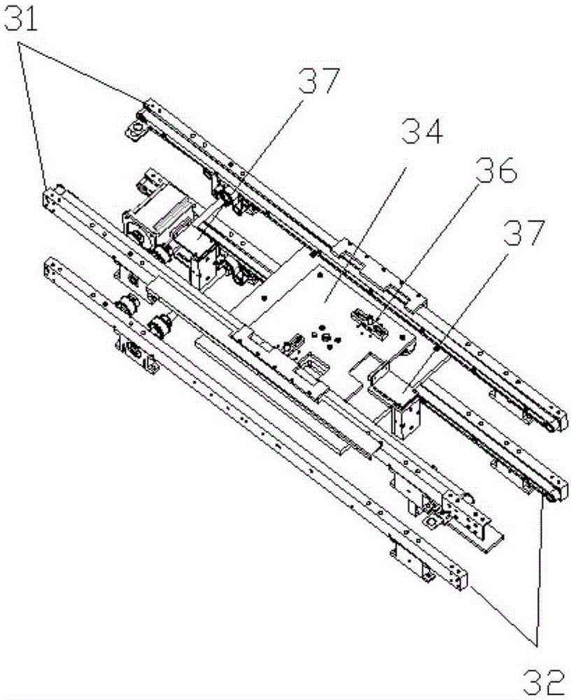
[0033] figure 1 Embodiment 1 of the mobile phone auxiliary material placement system for visual positioning, including the main frame 1, the auxiliary material stripping mechanism 2, the feeding and discharging mechanism 3, the placement actuator 4, the visual positioning mechanism 5, the controller (not shown in the figure), the host Frame 1 is a three-dimensional frame with X-axis, Y-axis, and Z-axis directions; six auxiliary material stripping mechanisms 2 are installed on the front of the main frame 1, and the feeding and discharging mechanism 3 passes through the middle of the main frame 1 and is adjacent to the rear of the auxiliary material stripping mechanism 2 The auxiliary material belt, the feeding and discharging mechanism 3 is provided with a placement execution area close t...


PUM


Abstract

The invention belongs to the field of mobile phone shell assembling equipment, and particularly relates to a visual-positioning mobile phone accessory attaching system. The visual-positioning mobile phone accessory attaching system comprises a hardware part and a software part. The hardware part comprises a main rack, a plurality of accessory stripping mechanisms, a feeding and discharging mechanism, an attaching executing mechanism, a visual-positioning mechanism and a controller. The software part comprises a hard configuration management module, a mobile phone accessory management module, a hand and eye calibration module and a work driving module. According to the visual-positioning mobile phone accessory attaching system, the manner that the accessory stripping mechanisms and the attaching executing mechanism with a plurality of suction nozzles are integrated on the main rack, attaching of various accessories can be completed at a time through one machine, and in addition, due to the fact that the accessory stripping action and the attaching action are independent from each other and work is completed in a division manner, the visual-positioning mobile phone accessory attaching system has the remarkable beneficial effects that precision is high, accessory waste is small, the requirement for the accessory manufacturing technology is low, the wire change cost is low, accessory stripping and accessory attaching are conducted in parallel and efficiency is high compared with a traditional accessory attaching system. In the traditional accessory attaching system, one machine is used for attaching one accessory; accessory stripping and accessory attaching are conducted in series; no machine vision exists, or a simple vision system is arranged, and generally, a camera is installed on a mechanical arm; and photographing is needed before each time of material taking.

Description

technical field [0001] The invention belongs to the field of mobile phone assembly equipment, and specifically refers to a visual positioning mobile phone auxiliary material placement system. Background technique [0002] The traditional auxiliary material sticking equipment usually sticks one kind of auxiliary material on one machine, and the stripping and sticking actions are serial, without a vision system or with a simple vision system (the camera follows the mechanical arm, and takes a photo to locate the auxiliary material to be sucked before peeling off the material. ), this type of system has inherent defects. One device can only paste one kind of auxiliary material. Usually, each model of mobile phone case needs to be pasted with multiple auxiliary materials. It needs to purchase multiple such placement machines to complete, and the cost performance is low. In addition, because the auxiliary material stripping action of this system is that the auxiliary material gra...

Claims


Application Information

Patent Timeline
IPC IPC(8): B65C9/42B65C9/08B65C9/26
Inventor 赵先平黄弢高锋
Owner DONGGUAN GOSUNM MACHINERY EQUIP CO LTD
Why Eureka
Try Eureka