Exercise apparatus and technique

a technology of exercise apparatus and muscle, applied in the field of exercise apparatus and technique, can solve the problems of not providing a controlled level of muscular exertion, the disadvantage of expensive equipment, and always providing the same resistance when moving in any direction or location, so as to reduce patellofemoral discomfort, avoid irritation or damage to the body, and improve mobility

Inactive Publication Date: 2008-05-08
KINETICS
View PDF17 Cites 48 Cited by
  • Summary
  • Abstract
  • Description
  • Claims
  • Application Information

AI Technical Summary

Benefits of technology

[0030] It is a still further object of the invention to provide a technique and apparatus for reducing patellofemoral discomfort and to improve mobility of persons suffering from patellofemoral pain.
[0031] In accordance with the above and further objects of the invention, one embodiment of exercise device is part of or may be attached to a brace for a body part. It may include means for fastening the exercise device to a limb brace or brace for another body part to control the amount of force needed to flex or extend the braced extremity or limb or other body part about a joint. The means for fastening may include pads and means for adjusting the location of the pads to avoid irritation or damage to the body such as irritation of burns. In a preferred embodiment, the means for controlling the amount of force includes one or more frictional resistance members that are removably attachable to a conventional brace to provide a desired resisting force to movement.

Problems solved by technology

The apparatus of U.S. Pat. No. 4,718,665 relies on friction belts instead of weights and thus avoids the disadvantages of continuing the force in the absence of motion and being unidirectional but still has the disadvantage of always providing the same resistance when moving regardless of direction or location in a cycle of movement.
This type of equipment has the disadvantage of being expensive, and under some circumstances, of not providing a controlled level of muscular exertion appropriate for the position of the parts being exercised since it is stationed on a fixed surface such as the floor.
This type of prior art exercise equipment has the disadvantages of: (1) continuously providing resistance of the same amount regardless of the position of the limb being exercised; (2) continuance of the force when the patient stops moving if the weight is elevated; and (3) being only uni-directional in a concentric (shortening muscle) sense.
This technique has several disadvantages under certain circumstances, such as: (1) continuing a resistive force after motion has stopped; (2) being adaptable only to open kinetic chain exercise; (3) being dependent to some extent on controlled speed of movement to provide the appropriate resistance; (4) the equipment is fixed to a particular locality when in use, as well as to the patient; (5) the equipment is bulky and cannot be easily moved from place to place; and (6) the user may inadvertently use other muscles to change the exercise pattern because the muscle cannot be easily isolated with equipment mounted to equipment on which the patient sits or stands or to the ground since the patient may be able to exert leverage with another part of the body.
This technique also has the disadvantage of being too inflexible and not accommodating resistance programs developed for specific purposes; such as to strengthen fast twitch or slow twitch muscles individually or for a program prescribed to accommodate a particular limb position for development of particular muscles in a manner deviating from the motor performance curve.

Method used


Image

  • Exercise apparatus and technique
  • Exercise apparatus and technique
  • Exercise apparatus and technique

Examples


Embodiment Construction

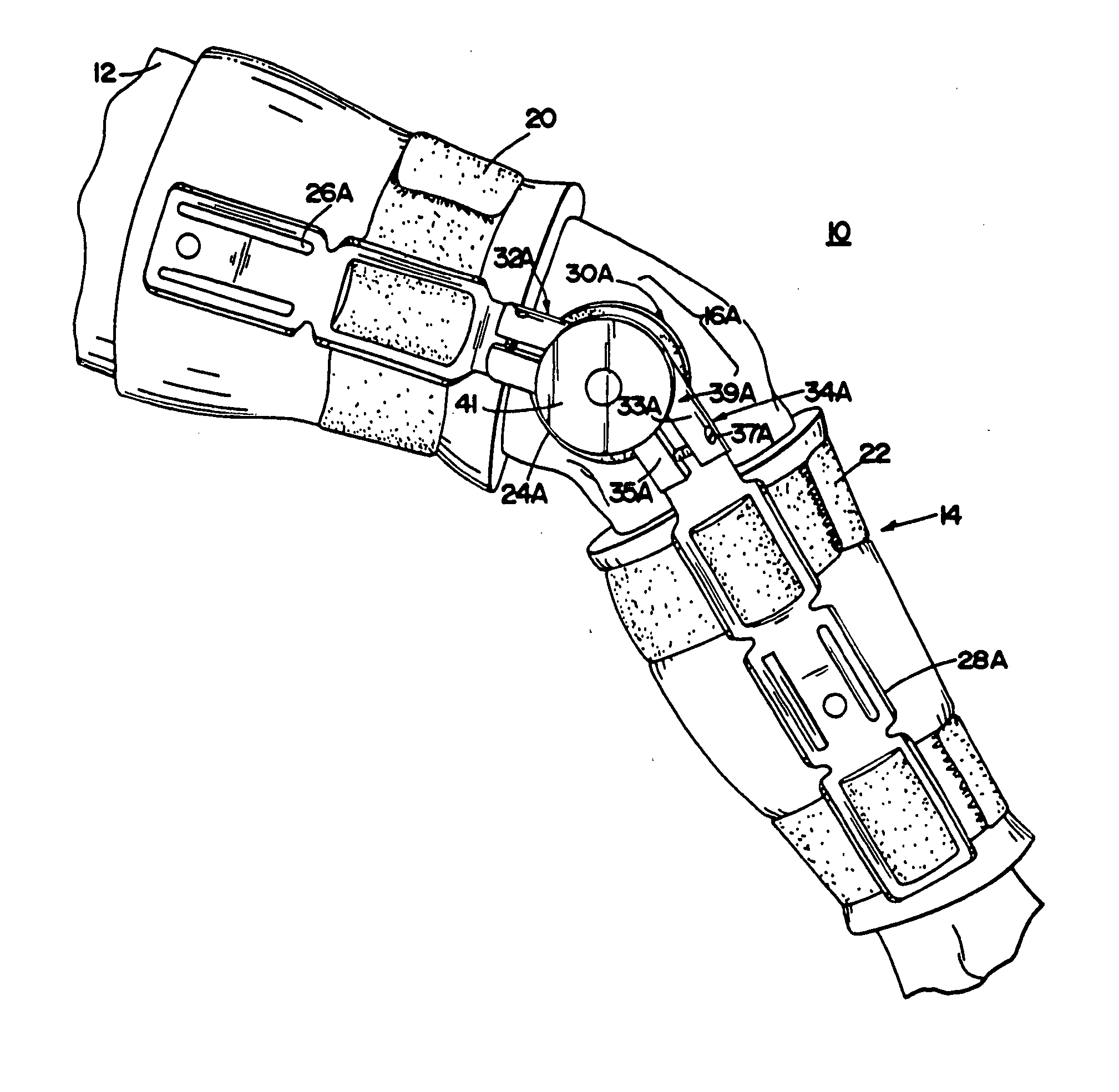
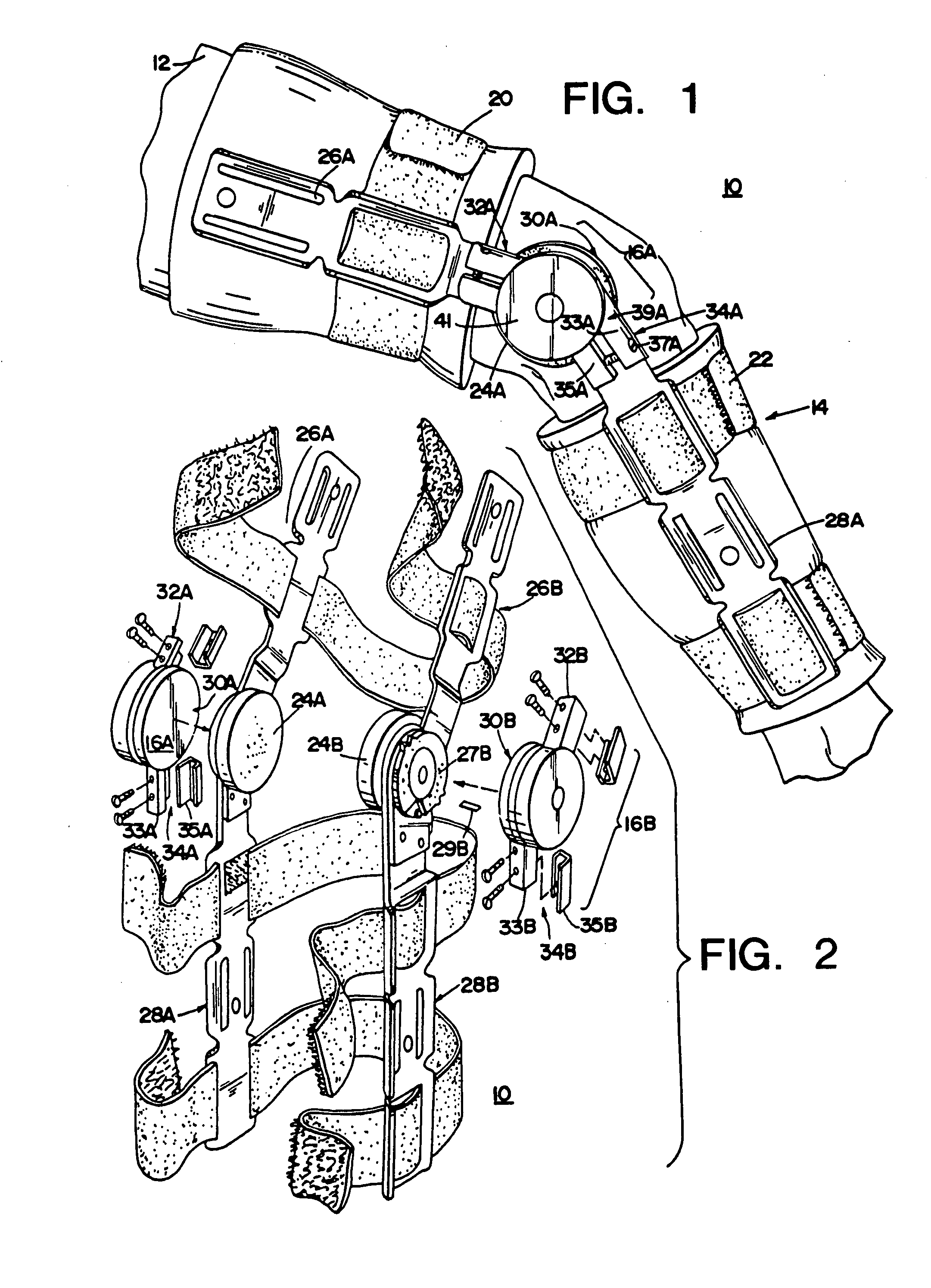
[0146] In FIG. 1, there is shown a fragmentary, perspective, partly-exploded view of an exercise assembly 10 mounted to a limb 12. The exercise assembly 10 includes a limb brace portion 14 and first and second exercise modules 16A and 16B, one on each side of the limb brace portion 14 (only 16A being shown in FIG. 1). In the preferred embodiment, the limb brace 14 is a standard brace that is not a part of the invention by itself except insofar as it cooperates with one or more removable exercise modules such as the exercise modules 16A and 16B.

[0147] The removable exercise modules 16A and 16B mount to the limb brace portion 14 which in this embodiment is a leg and thigh brace to control the resistance needed by limb 12 to move the brace portion 14 for limited movement about a knee. In the preferred embodiment, the resistance to movement is provided by frictional resistance.

[0148] The limb brace 14 includes a first support means 20, a second support means 22 and two pivotal joints ...


PUM


Abstract

To provide controlled amounts of resistance to movement in exercise equipment or in orthotic devices, a control module has cooperating resistance elements. The force between the elements is varied in accordance with the position of the elements with respect to each other. For example the control module can connect two splints of a knee brace so that the resistance to flexion and extension are programmed in accordance with the position of the leg and thigh with respect to each other.

Description

RELATED CASES [0001] This application is a divisional of U.S. patent application Ser. No. 09 / 379,851 filed Aug. 24, 1999, which is a divisional of U.S. patent application Ser. No. 08 / 665,076 filed Jun. 14, 1996, now U.S. Pat. No. 5,954,621, which is a continuation-in-part of U.S. application Ser. No. 08 / 494,528 filed Jun. 23, 1995, now U.S. Pat. No. 5,980,435, which is a continuation-in-part of U.S. application Ser. No. 08 / 271,022 filed Jul. 6, 1994, now U.S. Pat. No. 5,976,063, which is a continuation-in-part of U.S. application Ser. No. 08 / 089,852 filed Jul. 9, 1993, now U.S. Pat. No. 5,788,618 for EXERCISE APPARATUS AND TECHNIQUE by inventors Frank E. Joutras and Ronald J. Hruska, Jr.BACKGROUND OF THE INVENTION [0002] This invention relates to apparatuses and methods for providing controlled exercise and support. [0003] Braces for jointed anatomical limb segments such as the leg and thigh or the arm and forearm are known. The braces have joints that permit motion of the limb segm...

Claims


Application Information

Patent Timeline
Patent Type & Authority Applications(United States)
IPC IPC(8): A61H1/02
CPCA61H1/02A61H1/024A61H1/0266A61H1/0277A61H3/00A63B2220/16A61H2201/5007A61H2201/5058A63B21/015A63B2220/13A61H2201/165
Inventor JOUTRAS, FRANK EDWARDHRUSKA, RONALD J. JR.
Owner KINETICS
Why Eureka
Try Eureka