Electrical connector assembly with pick up cap

a technology of electric connectors and pick-up caps, which is applied in the direction of sustainable manufacturing/processing, coupling device connections, and final product manufacturing, etc. it can solve the problems of short time needed for curing adhesive films, inability to meet the requirements of connectors, etc., to achieve convenient efficient mounting of connectors.

Active Publication Date: 2007-09-04
HON HAI PRECISION IND CO LTD
View PDF12 Cites 17 Cited by
  • Summary
  • Abstract
  • Description
  • Claims
  • Application Information

AI Technical Summary

Benefits of technology

[0017]Accordingly, an object of the present invention is to provide an electrical connector assembly which has an electrical connector and a pick up cap mounted on the connector, wherein the pick up cap is configured to facilitate efficient mounting of the connector and pick up cap onto a circuit substrate such as a printed circuit board (PCB).
[0018]To achieve the above-mentioned object, an electrical connector assembly in accordance with a preferred embodiment comprises a land grid array (LGA) connector and a pick up cap. The connector comprises an insulative housing, a plurality of electrical contacts received in the housing, and a metal clip having a generally rectangular window in a middle thereof. The housing defines a generally rectangular cavity for receiving an electronic package such as an LGA central processing unit (CPU) therein. A multiplicity of passageways is defined in a portion of the housing under the cavity, the passageways receiving a corresponding number of the contacts therein. The clip is disposed on the housing to press the CPU upon the contacts. The pick up cap is engagingly mounted onto the connector and has a generally rectangular planar body. The planar body has a plane top surface and a bottom surface opposite to the top surface. Two generally rectangular first holes are defined in each of opposite lateral sides of the planar body. Two generally rectangular second holes are defined in a front end of the planar body. Two generally rectangular third holes are defined in a rear end of the planar body. Each third hole is located nearer an outer side edge of the planar body than both corresponding second holes. Each second hole is larger than each of the first and second holes. When the pick up cap is engagingly mounted onto the connector, the first, second and third holes are in communication with the window of the clip. A vacuum suction device can engage the top surface of the pick up cap, to move the connector assembly to a desired location on a circuit substrate such as a printed circuit board (PCB). When curing the adhesive film at high temperature in a convection cabinet using infrared radiant heaters, heated air can flow through the first, second and third holes to a bottom portion of the connector, thereby quickly and uniformly curing the adhesive film. Accordingly, when the entire assembly is subsequently processed in a wave solder machine or drag soldering equipment, reliable electrical connection between the contacts of the connector and the metal contact pads of the PCB is produced. Furthermore, when said entire assembly is cooled, heated air can be quickly dissipated out through the first, second and third holes of the pick up cap. That is, said entire assembly can be quickly cooled. The efficiency of mounting of the connector onto the PCB is thereby enhanced.

Problems solved by technology

Thus the connector does not have a suitably smooth, integral top surface for engagement by a vacuum suction device.
Generally, the time needed for curing the adhesive film is short.
Thus, the adhesive film is liable to cure non-uniformly.
This increases the time needed for cooling the assembly, which reduces the efficiency of mounting of the connector 8 onto the PCB.

Method used


Image

  • Electrical connector assembly with pick up cap
  • Electrical connector assembly with pick up cap
  • Electrical connector assembly with pick up cap

Examples


Embodiment Construction

[0027]Reference will now be made to the drawings to describe the present invention in detail.

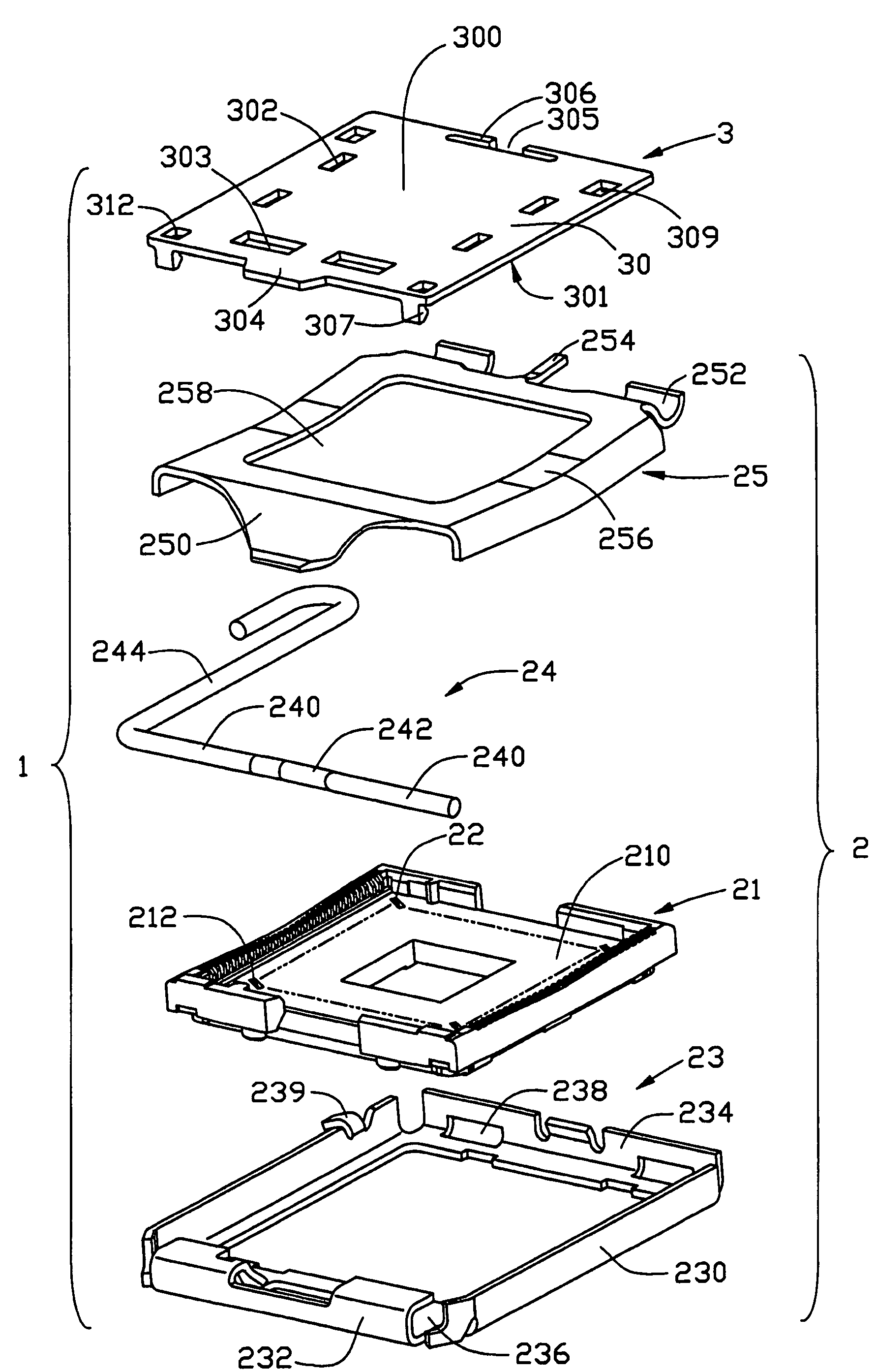
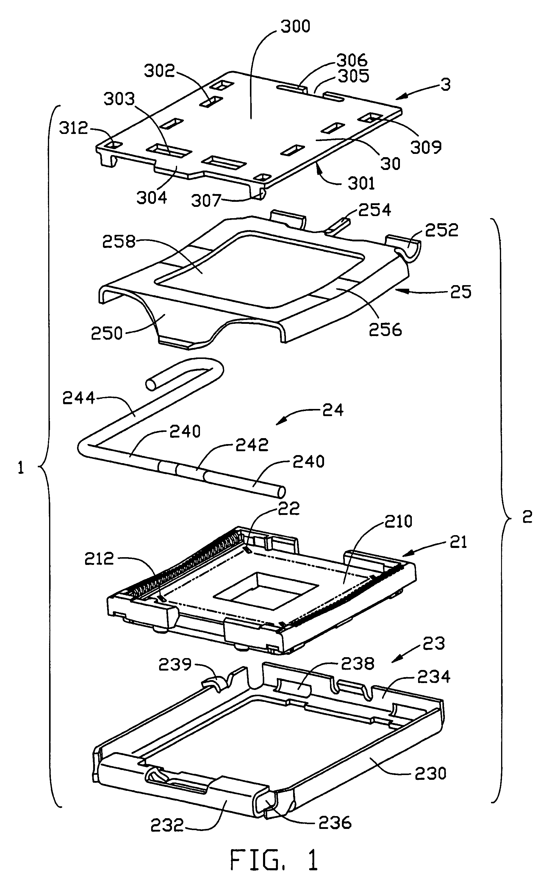
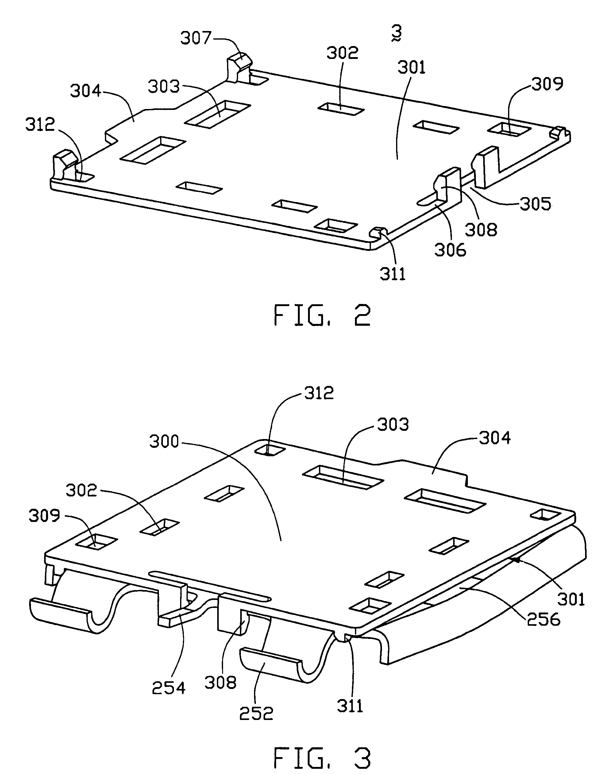
[0028]FIG. 1 is an exploded, isometric view of an electrical connector assembly 1 in accordance with the preferred embodiment of the present invention. The connector assembly 1 comprises a land grid array (LGA) connector 2 and a generally rectangular pick up cap 3. The pick up cap 3 is mounted onto the connector 2, for providing a plane top surface to be engaged by a vacuum suction device. The connector assembly 1 can thereby be moved onto a circuit substrate, such as a printed circuit board (PCB) (not shown), on which the connector 2 is to be mounted.

[0029]The connector 2 comprises a generally rectangular insulative housing 21, a plurality of electrical contacts 22 received in the housing 21, a metal stiffener 23 partly covering and reinforcing the housing 21, a lever 24 pivotably received in an end of the stiffener 23, and a metal clip 25 pivotably mounted to an opposite end of the stiffen...


PUM


Abstract

An electrical connector assembly (1) includes an LGA connector (2) having a metal clip (25) and a pick up cap (3). The pick up cap has a planar body (30) forming a plane top surface (300). Several holes (302, 303, 309) are defined in the planar body. When the pick up cap is engagingly mounted onto a top portion of the connector, the holes are in communication with a window (258) of the clip. A vacuum suction device can engage the top surface of the pick up cap to move the connector assembly to a desired location on a PCB. When curing adhesive film at high temperature, heated air can flow through the holes to a bottom portion of the connector. Reliable electrical connection between the contacts of the connector and the metal contact pads of the PCB is subsequently produced in a wave solder machine or drag soldering equipment.

Description

CROSS-REFERENCE TO RELATED APPLICATION[0001]The present invention is related to a co-pending U.S. Pat. No. 6,877,990 B2 filed on Jul. 3, 2003, entitled “LAND GRID ARRAY CONNECTOR ASSEMBLY WITH PICK UP CAP,” invented by Fang-Jwu Liao, and assigned to the same assignee as the present invention.BACKGROUND OF THE INVENTION[0002]1. Field of the Invention[0003]The present invention relates to an electrical connector assembly which comprises an electrical connector and a pick up cap, the pick up cap being mounted to the connector for providing a plane top surface to be engaged by a vacuum suction device, whereby the connector assembly can be moved onto a circuit substrate such as a printed circuit board (PCB) on which the connector is to be mounted.[0004]2. Description of the Related Art[0005]On many production lines, electronic components such as electrical connectors are mounted onto circuit substrates such as printed circuit boards (PCBs) by surface mount technology (SMT), as disclosed ...

Claims


Application Information

Patent Timeline
Patent Type & Authority Patents(United States)
IPC IPC(8): H01R13/44H01R12/16H01R43/20H05K3/30H05K3/34
CPCH01R43/205H05K3/303H01R12/7076H05K3/3494H05K2201/09127H05K2201/10189H05K2203/081H05K2203/082Y10S439/94Y02P70/50
Inventor LIAO, FANG-JWU
Owner HON HAI PRECISION IND CO LTD
Why Eureka
Try Eureka