Illuminated elevator including cold-cathode flourescent lamp

a technology of flourescent lamps and elevators, which is applied in the direction of discharge tubes luminescnet screens, lighting and heating apparatus, transportation and packaging, etc., can solve the problems of inconvenient elevator users, fluorescent lamps start to go off or flicker, and excessive current damages the cathode, so as to reduce maintenance work

Inactive Publication Date: 2009-12-01
TOSHIBA ELEVATOR KK
View PDF71 Cites 10 Cited by
  • Summary
  • Abstract
  • Description
  • Claims
  • Application Information

AI Technical Summary

Benefits of technology

[0058]The present invention was made in view of the foregoing problems in the conventional art, and an object is to provide a lighting system of elevator which is prolonged in life to reduce maintenance work, and which has no problems to elevator users.
[0059]The present invention provides an elevator hall lantern which can be formed in a compact and thin structure and installed at a landing hall easily and efficiently, and which can easily realize irradiation with a white light.
[0060]An object of the present invention is to provide an elevator threshold which enables passengers to easily recognize a gap between a car threshold and a landing threshold, provides illumination by high illuminance to facilitate recognition of a generated step, illuminates a full width of a threshold to be easily seen in design, and secures safety of the passengers.

Problems solved by technology

It is because an excessive current is necessary at the starting time of the fluorescent lamp, and this excessive current damages a cathode.
Therefore, the fluorescent lamp starts to go off or flicker, which necessitates replacement.
During such maintenance work, the entire elevator must be stopped, and it is very inconvenient for elevator users because the elevator cannot be used.
From the standpoint of safety, the maintenance engineer must carry out the maintenance work, and much time and labor are required even for only the replacement of the fluorescent lamp.
Consequently, much time and labor are required.
However, the general fluorescent lamp cannot be lit immediately because irregular flickering occurs during lighting.
Thus, in the general fluorescent lamp which irregularly flickers during lighting, it is impossible to employ a form of displaying information by regular flickering.
In the general fluorescent lamp, an average life is short, i.e., 6000 hours, and not only maintenance and replacement require time and labor but also safety measures cannot be taken for the passengers when the lamp is unlit.
Furthermore, in the illumination by the array of incandescent lamps, the illumination is provided by the light sources arranged at random, and design is inferior.
Thus, there is a problem in adoption.
In this case, however, the following problems arise.(1) The fluorescent lamp (hot cathode-ray tube) 1164 for general home use becomes large overall including a stabilizer to light the fluorescent lamp 1164 because not only the fluorescent lamp itself is large but also an excessive current is necessary at the starting time of the fluorescent lamp.
It is because the excessive current is necessary at the starting time of the fluorescent lamp as described above, and the excessive current damages a cathode.
However, its attachment to the elevator car has not been devised yet.
Even if it is attached, since maintenance space cannot be secured, the replacement work of the fluorescent lamp 1164 becomes difficult, which causes inconvenience that the elevator is stopped for a long time.
As a result, the outside dimension of the exterior panel 1253 becomes large, creating a possibility of interferences with the devices such as the compensation rope tension pulley 1263 in the hoistway pit.
It is because an excessive current is necessary at the starting time of the fluorescent lamp, and the excessive current damages a cathode.
As a result, the fluorescent lamp for general home use is burned out about once every year.
If the number of elevators to be installed is large, replacement work must be frequently carried out.
Additionally, because of frequent replacement work of the lamp, maintenance costs become high, and running of the elevator must be stopped for each replacement work.
However, because of a short life of the fluorescent lamp, replacement work must be frequently carried out.
However, as it is originally constituted to surface-illuminate a screen through an optical waveguide, even if it is directly used, an irradiation angle of the cold-cathode fluorescent lamp is small, and an uneven light is generated on the illumination plate surface.
Conventionally, however, since the blackout lamp is disposed on the ceiling portion of the cage, illuminance becomes short especially at the floor surface portion of the cage, i.e., at the foot portion of a passenger.
At the time of a blackout, the foot portion is dark, and the passenger feels uneasier.
Thus, illuminance for the operation panel also becomes short, and a position of the operation panel and a content of the button are difficult to be determined, which only confuses the passenger.

Method used


Image

  • Illuminated elevator including cold-cathode flourescent lamp
  • Illuminated elevator including cold-cathode flourescent lamp
  • Illuminated elevator including cold-cathode flourescent lamp

Examples


first embodiment

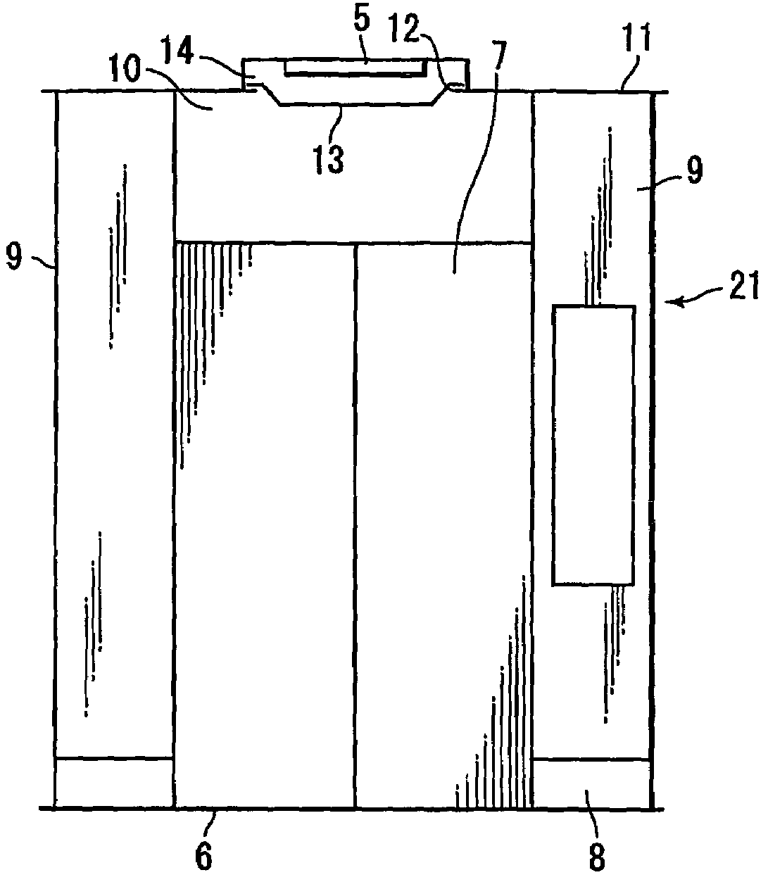
[0138]an elevator lighting system of the present invention will be described with reference to FIGS. 1 to 3.

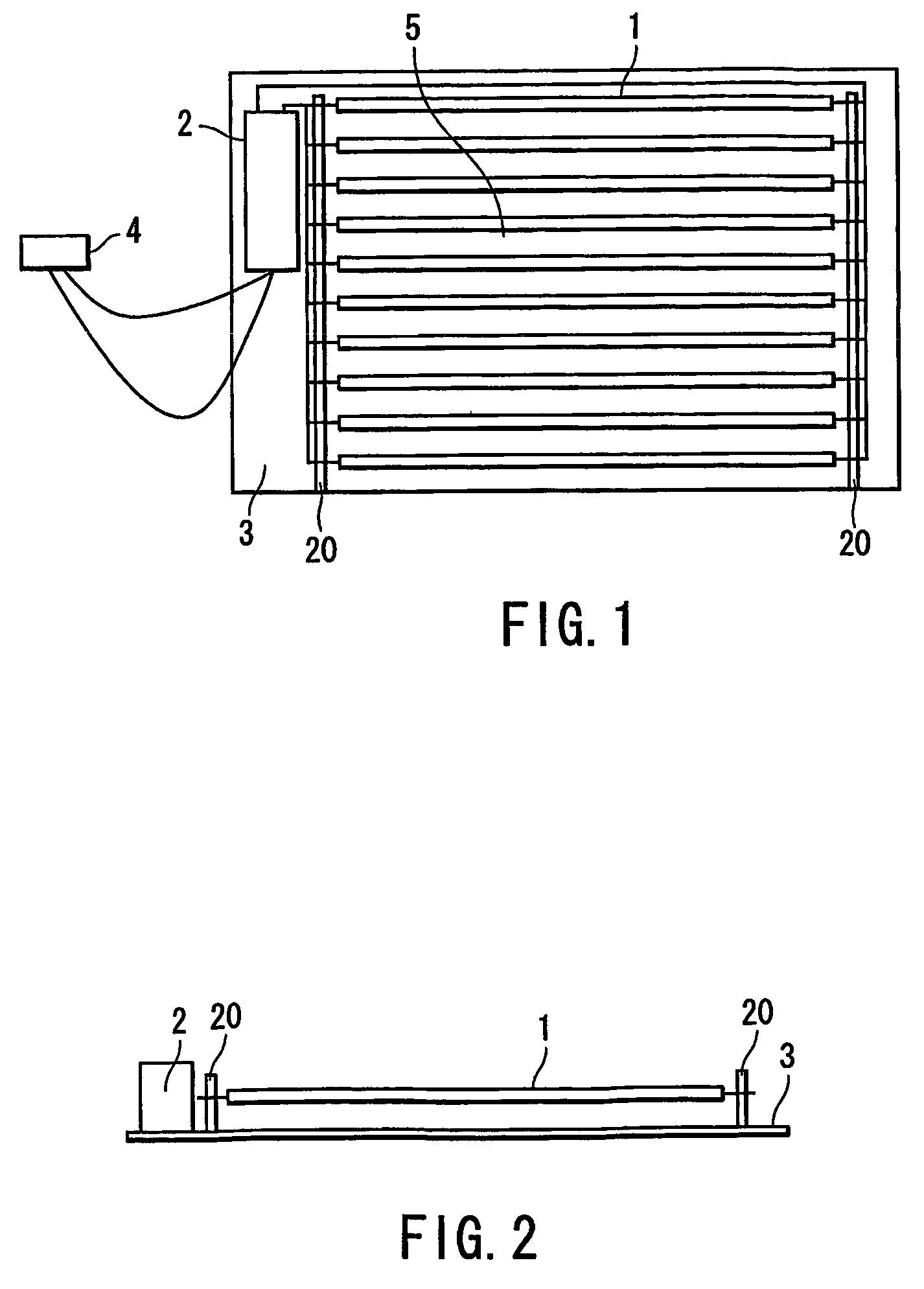
[0139]FIG. 1 is a front view of the first embodiment of the elevator lighting system, FIG. 2 is a side view of the first embodiment of the elevator lighting system, and FIG. 3 is a front view of a car in which the elevator lighting system is arranged.

[0140]A lighting system 5 comprises at least ten straight-tube cold-cathode fluorescent lamps 1, a stabilizer 2 which lights the cold-cathode fluorescent lamp 1, a reflection plate 3 which reflects a visible light radiated from the cold-cathode fluorescent lamp 1, a connector 4 which supplies power to the stabilizer 2, and a support base 20 which supports the cold-cathode fluorescent lamp 1.

[0141]The cold-cathode fluorescent lamp 1 comprises at least a translucent discharge container having a diameter of about 1 mm to 6 mm, a pair of cold cathodes (not shown) sealed to both sides of the discharge container, a fluorescent material ...

second embodiment

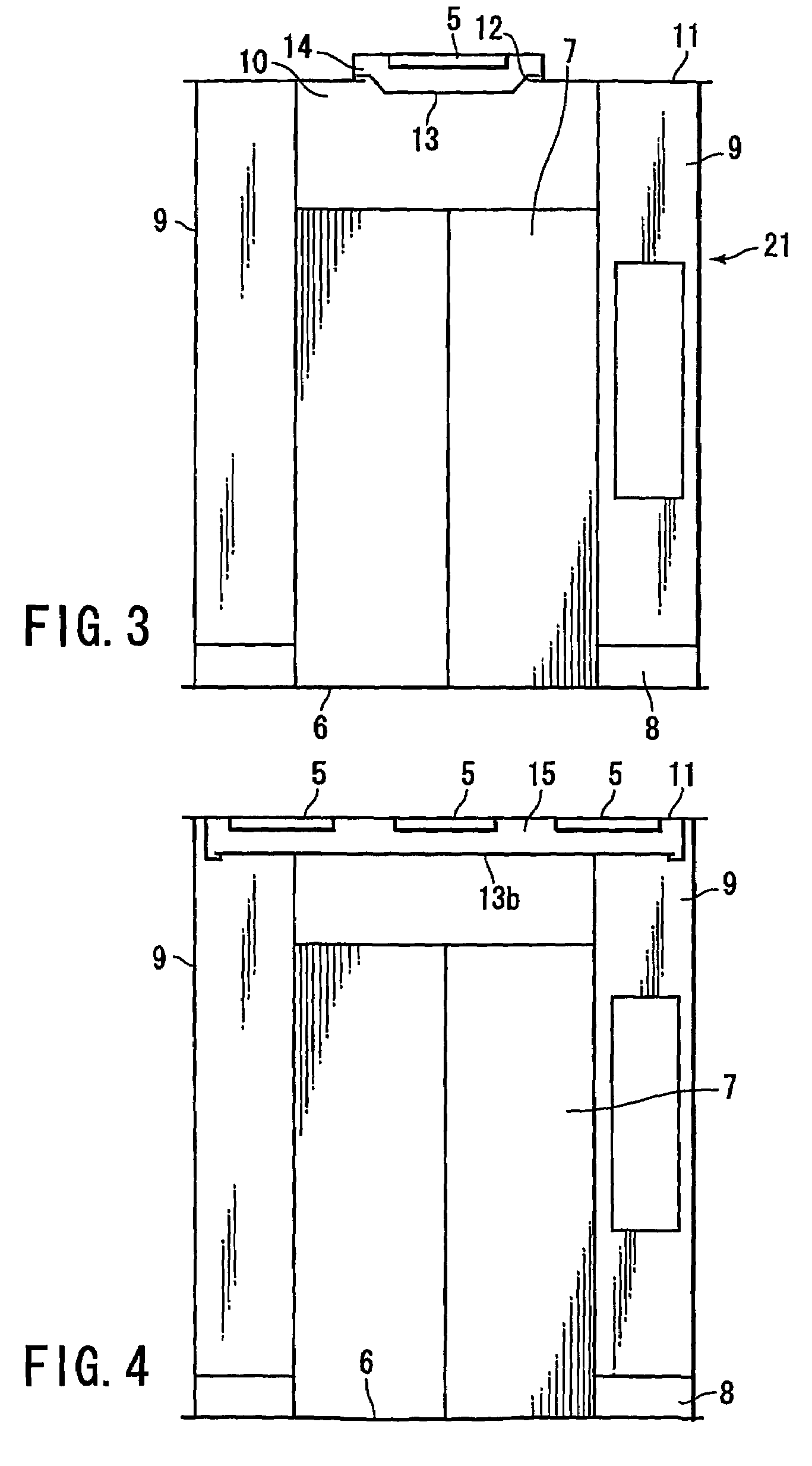
[0160]Next, description will be made of a constitution of a lighting system of an elevator of the present invention by referring to FIG. 4.

[0161]In the embodiment described below, components similar to those of the first embodiment are denoted by similar reference numerals, and overlapped description will be omitted.

[0162]As shown in a front view of FIG. 4, a luminous ceiling 15 is disposed to radiate a light from a roughly full surface of a ceiling of a cage. An illumination plate 13b is disposed below the luminous ceiling 15. In this ceiling plate 15, a plurality of lighting units 5 are arranged to match a shape of the illumination plate 13b.

[0163]According to this constitution, effects similar to those of the first embodiment can be obtained.

third embodiment

[0164]Next, description will be made of a lighting system of an elevator of the present invention by referring to a front view of FIG. 5.

[0165]A feature of the third embodiment is that a lighting unit 5 is directly attached to a top plate 11.

[0166]The lighting unit 5 is fixed to the top plate 11.

[0167]According to such a constitution, effects similar to those of the first embodiment can be obtained.

[0168]Since the lighting unit 5 does not project from the top plate 11 to the outside of a cage, it is possible to reduce top clearance which is a distance between the cage and a ceiling of a hoistway. Since there is no projected portion on the cage, design of car appearance can be improved.


PUM


Abstract

An illuminated elevator lighting system including an elevator cage, a plurality of cold-cathode fluorescent lamps disposed on a ceiling surface of the cage and arrayed in parallel, a reflection plate which reflects an illumination light from the cold-cathode fluorescent lamp, and a stabilizer which lights the cold-cathode fluorescent lamp.

Description

TECHNICAL FIELD[0001]The present invention relates to a lighting system of an elevator.[0002]The present invention relates to a hall lantern of an elevator which is disposed at, for example, a landing hall of the elevator to display a running situation such as a car arrival to a user of the elevator.[0003]The present invention relates to a threshold structure of each of an elevator landing and a cage.[0004]Additionally, the present invention relates to a lighting system in an elevator car.[0005]Further, the present invention relates to a car exterior lighting system of an elevator.[0006]The present invention relates to a lighting system of an elevator cage.[0007]Furthermore, the present invention relates to a blackout lamp device of an elevator which is lit at the time of a blackout to illuminate the inside of a cage.BACKGROUND ART<Lighting System of Elevator>[0008]Conventionally, a general fluorescent lamp (hot cathode-ray tube) for home use has been used for a lighting syste...

Claims


Application Information

Patent Timeline
Patent Type & Authority Patents(United States)
IPC IPC(8): F21V7/20F21V29/00B66B11/02B66B13/30F21V29/505
CPCB66B11/0233B66B13/306B66B13/301B66B13/30B66B11/02
Inventor ENDO, MASAHIKOIKEDA, KYOICHIOKADA, KENICHIOGAWA, HIROYUKI
Owner TOSHIBA ELEVATOR KK
Why Eureka
Try Eureka