LED (Light Emitting Diode) lamp module radiator

An LED lamp module, LED lamp technology, applied in lighting and heating equipment, cooling/heating device of lighting device, lighting device, etc. The effect of large heat dissipation area, weight reduction, and convenient cleaning work

Inactive Publication Date: 2015-06-03
SUZHOU CHENGYUAN PHOTOELECTRIC TECH
View PDF4 Cites 10 Cited by
  • Summary
  • Abstract
  • Description
  • Claims
  • Application Information

AI Technical Summary

Problems solved by technology

[0002] Most of the traditional lighting uses incandescent lamps, but with the development of technology, LED lamps have been widely used in various lighting fields due to their high luminous efficiency, low energy consumption, no need for high voltage, and high safety. When some large areas are illuminated, the work of these LED lights is heavy. The life of the LED light source is closely related to the working temperature of the node. At present, only 15%-25% of the electric energy of the LED is converted into light energy during the working process, and the rest of the light Almost all the energy is converted into heat energy, which makes the temperature of the LED lamp rise, and the temperature increases by 10 degrees, and its reliability will be reduced by half. Especially in high-power LEDs, heat dissipation is a big problem. If the heat dissipation is not good, it will directly affect the LED. Rapid aging, reduced stability, poor heat dissipation and easy to cause light decay, which seriously affects the life of the lamp. For example, the LED lamp modular radiator described in the application number 201110200072.7 has a heat sink, but the heat dissipation structure Single, the heat dissipation effect still needs to be improved. For the module of multiple LED lights, the heat dissipation is huge, so more effective heat dissipation methods are needed to solve the problem

Method used


Image

  • LED (Light Emitting Diode) lamp module radiator
  • LED (Light Emitting Diode) lamp module radiator

Examples


Embodiment Construction

[0012] specific implementation plan

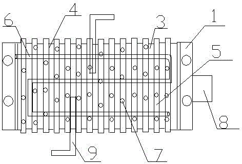
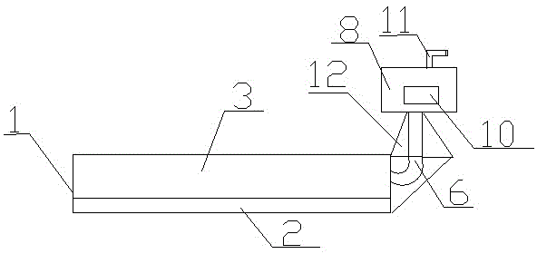
[0013] Such as figure 1 figure 2 The LED lamp module radiator includes a lamp holder template 1, an LED lamp panel 2 is provided on one side of the lamp holder template 1, a heat dissipation substrate 3 is provided on the other side of the lamp holder template 1, and a lamp holder One side of the template 1 is provided with an LED light panel 2 and the other side is provided with a heat dissipation substrate 3, which is conducive to timely transferring the heat generated by the LED light panel 2 to the heat dissipation substrate 3, and the heat dissipation through the heat dissipation substrate 3 is more convenient and efficient. 3 is provided with a groove 4, and the groove 4 is provided to facilitate the installation and disassembly of the heat sink 5, and also facilitates the cleaning work in the future. The groove 4 is provided with a heat sink 5, and the thickness of the heat sink 5 is The heat sink 5 with a thickness of 3mm-5mm is...


PUM


Abstract

The invention discloses an LED (Light-Emitting Diode) lamp module radiator, and relates to the field of lamp accessories. The LED lamp module radiator comprises a lamp holder template, wherein an LED lamp panel is arranged on one side of a lamp holder, a heat-dissipating substrate is arranged on the other side of the lamp holder template, a groove is formed in the heat-dissipating substrate, the groove is provided with radiating fins which are 3-5 millimeters thick, the heat-dissipating substrate is provided with two L-shaped heat-dissipating posts, the heat-dissipating substrate is further provided with a heat-dissipating pipeline, the heat-dissipating pipeline is filled with cooling liquid, the heat-dissipating pipeline is connected with a liquid storage tank, the liquid storage tank is provided with an air vent hole, and the liquid storage tank is further provided with a transparent window. The LED lamp module radiator has the advantages of reasonable structure, novel design, safety, reliability, environmental friendliness, less energy consumption, good heat-dissipating effect and easy application and popularization, adopts two natural cooling ways, liquid cooling and air cooling, for dissipating heat, and does not consume additional power.

Description

technical field [0001] The invention relates to the field of lamp accessories, in particular to a radiator for LED lamp modules. technical background [0002] Most of the traditional lighting uses incandescent lamps, but with the development of technology, LED lamps have been widely used in various lighting fields due to their high luminous efficiency, low energy consumption, no need for high voltage, and high safety. When some large areas are illuminated, the work of these LED lights is heavy. The life of the LED light source is closely related to the working temperature of the node. At present, only 15%-25% of the electric energy of the LED is converted into light energy during the working process, and the rest of the light Almost all the energy is converted into heat energy, which makes the temperature of the LED lamp rise, and the temperature increases by 10 degrees, and its reliability will be reduced by half. Especially in high-power LEDs, heat dissipation is a big pro...

Claims


Application Information

Patent Timeline
Patent Type & Authority Applications(China)
IPC IPC(8): F21V29/56F21V29/76F21V29/83F21Y101/02
Inventor 戴岳平
Owner SUZHOU CHENGYUAN PHOTOELECTRIC TECH
Why Eureka
Try Eureka