Heat dissipating structure of LED circuit board and LED lamp tube comprised thereof

Active Publication Date: 2010-03-18
KITAGAWA HLDG
View PDF5 Cites 37 Cited by
  • Summary
  • Abstract
  • Description
  • Claims
  • Application Information

AI Technical Summary

Benefits of technology

[0007]Accordingly, an object of the present invention is to provide a heat dissipating structure o

Problems solved by technology

Hence, the maintenanc

Method used


Image

  • Heat dissipating structure of LED circuit board and LED lamp tube comprised thereof
  • Heat dissipating structure of LED circuit board and LED lamp tube comprised thereof
  • Heat dissipating structure of LED circuit board and LED lamp tube comprised thereof

Examples


Embodiment Construction

[0018]In cooperation with attached drawings, the technical contents and detailed description of the invention are described thereinafter according to a number of preferable embodiments, being not used to limit its executing scope. Any equivalent variation and modification made according to appended claims is all covered by the claims claimed by the present invention.

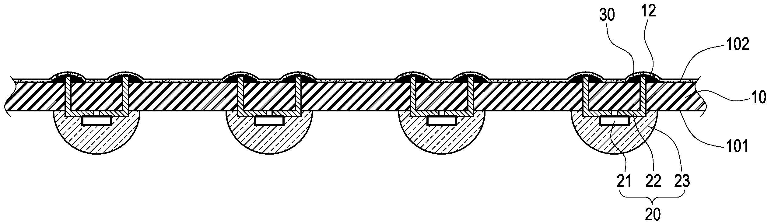
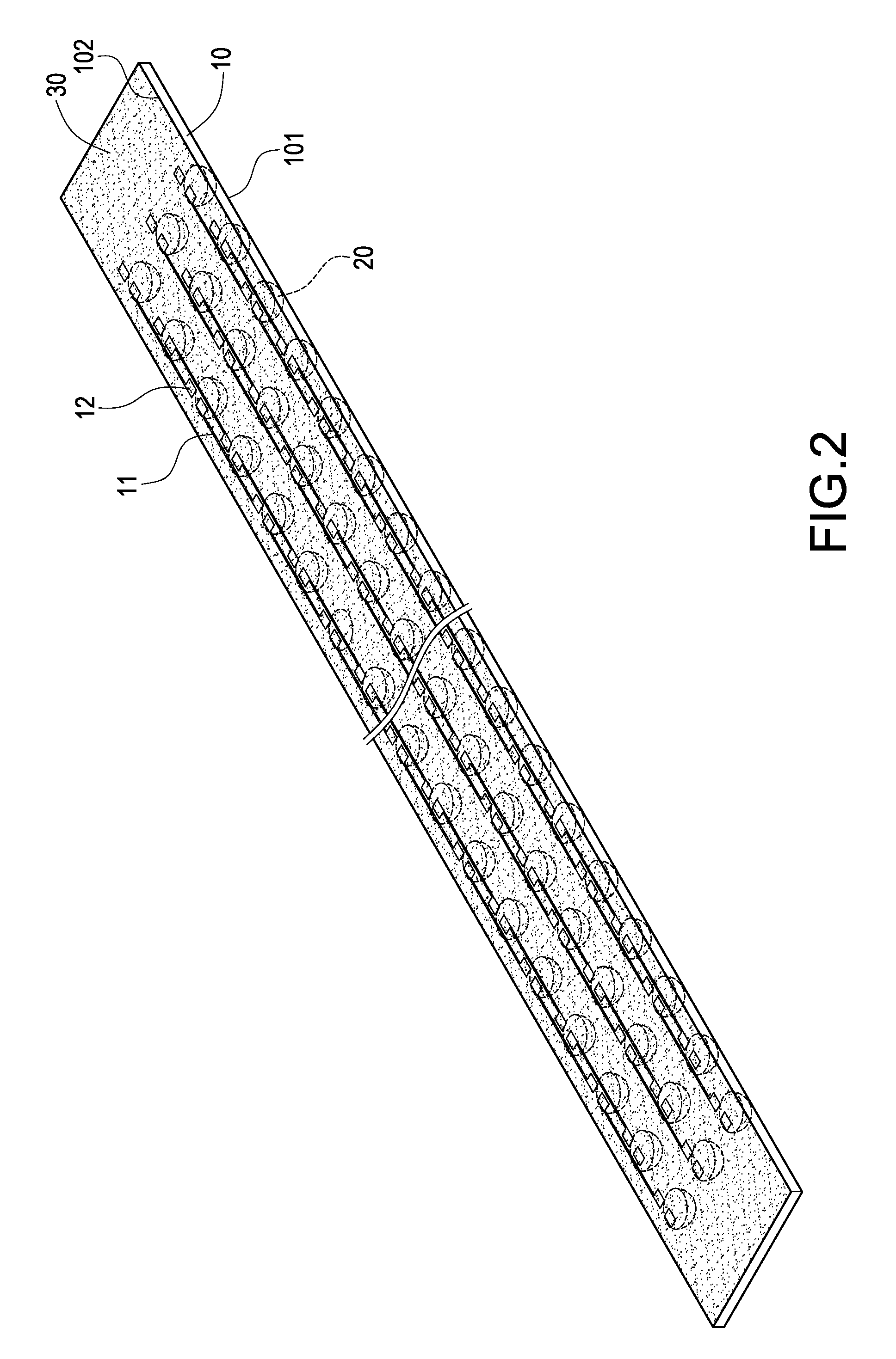
[0019]With refer to FIG. 2, a perspective view of a heat dissipating structure of an LED circuit board of the present invention is shown. The invention is a heat dissipating structure of an LED circuit board. A preferable embodiment of the invention comprises an LED circuit board 10, which has a light radiating surface 101 and a heat dissipating surface 102. A plurality of LEDs 20 are electrically mounted on the light radiating surface 101 of the LED circuit board 10 and are arranged with an interval. The heat dissipating surface 102 of the LED circuit board 10 is provided with copper foil 11 and soldering points 12. A c...


PUM


Abstract

A heat dissipating structure of an LED circuit board and a device applied in an LED tube which comprises an LED circuit board having a plurality of soldering points. The soldering points of the LED circuit board are covered a coating layer including Nanoparticles and a bonding agent. Accommodating the LED circuit board covering the coating layer in an LED lamp tube to accelerate dissipating the heat of the LED circuit board by the coating layer having the characters of high emitting rate, temperature resistance, and conductivity insulation. On the other hand, for the coating layer can increase the contacting areas of the soldering points with the air to enlarge the heat dissipation area of the LED circuit board to accelerate dissipating the heat.

Description

BACKGROUND OF THE INVENTION[0001]1. Field of the Invention[0002]The present invention generally relates to heat dissipation, in particular to a heat dissipating structure of an LED lamp.[0003]2. Description of Prior Art[0004]As light emitting diodes (LEDs) come with the features of low power consumption, power saving, long service time, small size and quick response etc., LED lamps gradually substitute traditional light sources, such as an LED lamp tube.[0005]With reference to FIG. 1 for the structure of LEDs applied in a lamp tube, a tube 10a includes a circuit board 20a on which a plurality of LEDs 30a are mounted, two bushings 40a separately sheathing both ends of the tube 10a. Each of the bushings 40a includes two conductive terminals 401a. The LED lamp tube is installed in a lamp holder by the conductive terminals 401a on both ends for electrically conducting a power source to the LEDs 30a and emitting light.[0006]Although light the LEDs 30a of the LED lamp tube only needs less...

Claims


Application Information

Patent Timeline
IPC IPC(8): H01J7/24
CPCB82Y99/00F21V29/85H05K2201/0257H05K2201/0209H05K3/3447H05K3/285H05K1/0209F21Y2105/001F21Y2101/02F21V5/04F21V3/02F21S8/031F21S4/003F21K9/17H05K2201/10106B82Y30/00F21V29/506F21V29/83H05K2201/10977F21Y2105/10F21K9/27F21Y2115/10
Inventor LIN, KUO-LENLIN, CHEN-HSIANGWANG, HWAI-MINGHSU, KENCHENG, CHIH-HUNG
Owner KITAGAWA HLDG
Why Eureka
Try Eureka