Heat sink

a heat sink and heat sink technology, applied in the field of heat sinks, can solve the problems of inconvenient use of milled heat sinks, inefficient or unreliable heat sinks, and an important issue of heat generated by a single microprocessor, so as to improve heat dissipation ability, less resistance to the flow of cooling air, and enhanced heat dissipation area

Inactive Publication Date: 2002-10-15
CHEUNG YUK WOON
View PDF3 Cites 39 Cited by
  • Summary
  • Abstract
  • Description
  • Claims
  • Application Information

AI Technical Summary

Benefits of technology

It is therefore an object of the present invention to provide a heat sink with an enhanced heat dissipation capability. In general, the preferred heat sink will have an enhanced heat dissipation area per given envelope volume and the heat dissipation members are arranged in a manner which are less resistant to the flow of cooling air. It is also an object of the present invention to provide a heat sink having highly efficient heat dissipation characteristics by obviating the drawbacks associated with non-integrally formed heat sinks. It is another object of the present invention to provide an integrally formed heat sink made by cold forging an appropriate heat conducting material which provides a very satisfactory heat dissipation characteristic. It is a further object of the present invention to provide a heat sink formed of a preferred alloy which demonstrates improved thermal dissipation characteristics after subjecting to formation by a cold forging process.

Problems solved by technology

However, with the ultra high density of circuit integration together with the high operating clock rates, the heat generated by a single microprocessor becomes an important issue.
Such heat sinks are inefficient or unreliable because of the imperfect junction between the discrete components.
With these practical limitations, milled heat sinks are not suitable for use with state-of-the-art microprocessors.
On the other hand, heat sinks formed by cutting and die casting have such poor production efficiency that it is not economically feasible to adopt them in large-scale industrial production.
While heat sinks made by hot extrusion are relatively inexpensive, it is however well known that the thickness and pitch of the fins are inherently limited such that the heat dissipating characteristics of such heat sinks are unsatisfactory.
While an electric fan is sometimes effective to increase the thermal dissipating rate, over-reliance on an electric fan can be dangerous as an electric fan is known to be noisy and have a limited operation life and reliability.
Any interruption of the fan may cause interruption or damage to the microprocessor which can be annoying and is undesirable.
Furthermore, the use of an electric fan also increases the power requirements of the computer as a whole and is undesirable for lap-top or pocket computers.

Method used


Image

  • Heat sink
  • Heat sink
  • Heat sink

Examples


Embodiment Construction

Preferred embodiments of the present invention will be explained by way of examples and with reference to the accompanying drawings, in which:

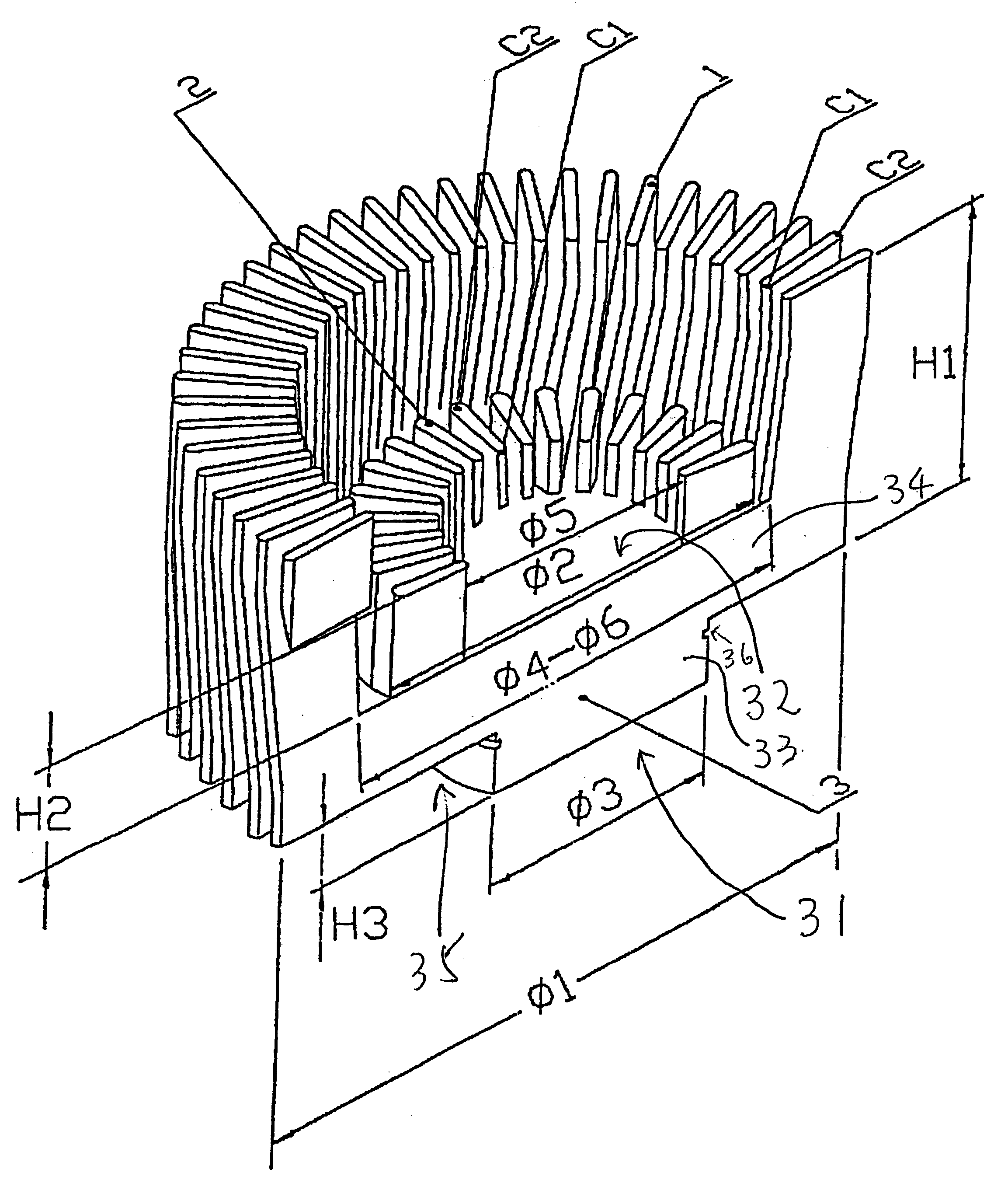
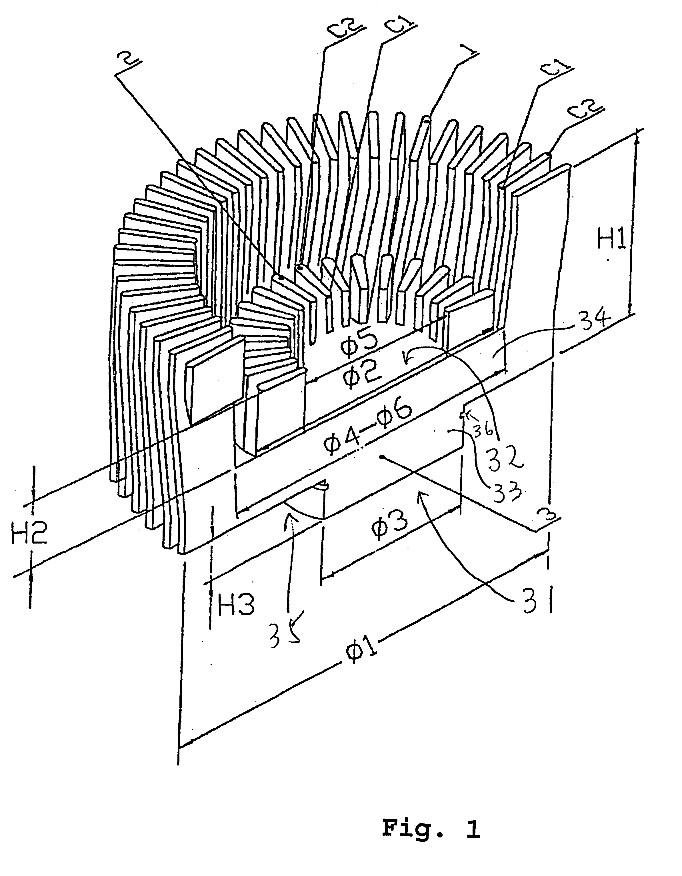
FIG. 1 is a perspective view of a first preferred embodiment of the heat sink of the present invention when viewed from the top (base portion being hidden);

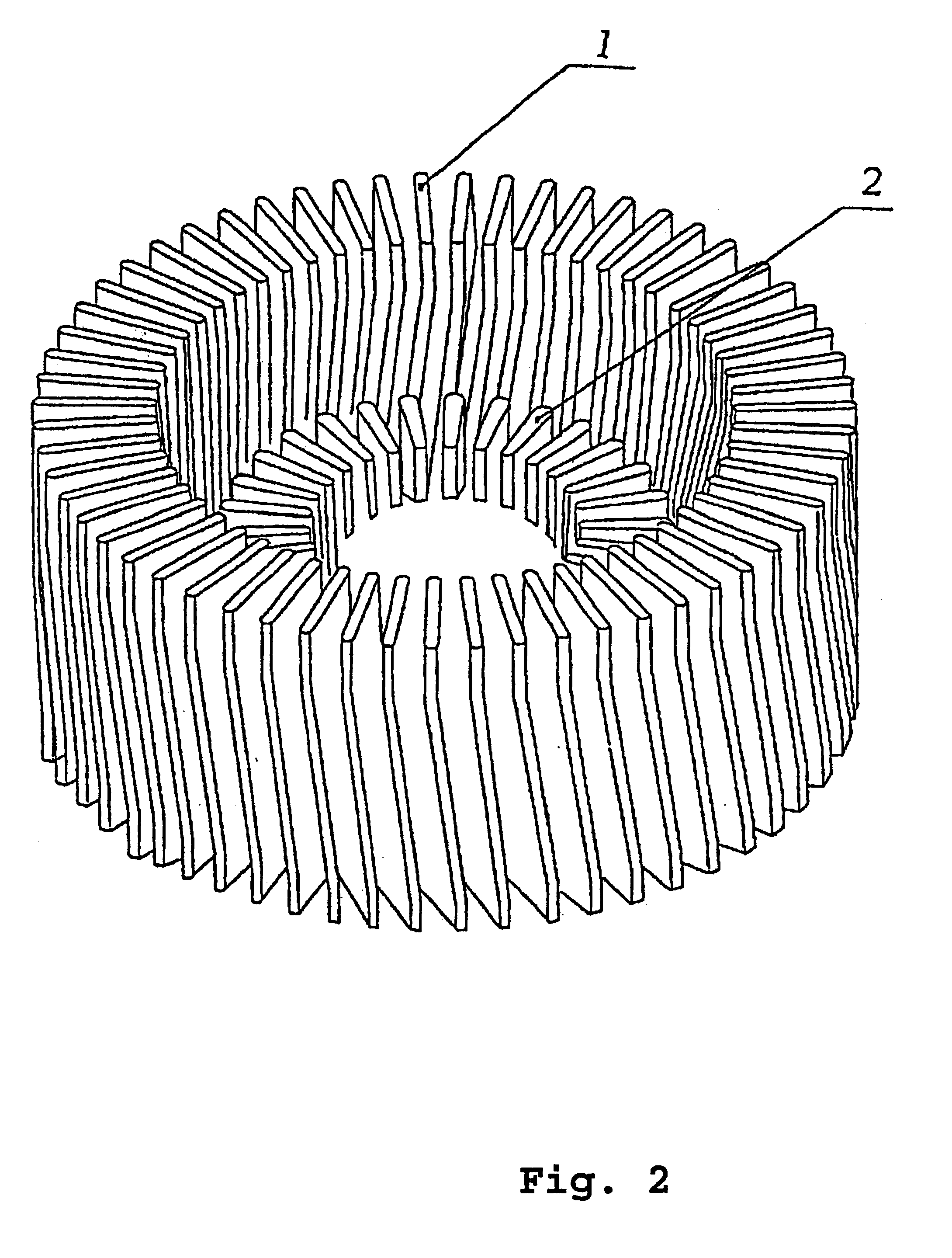
FIG. 2 is a perspective view showing the heat sink of FIG. 1 with part of the heat sink cut away at about the middle;

FIG. 3 is a side view of the heat sink of FIG. 1 with the rightof the figure showing the cross-section of the heat sink;

FIG. 4 is a plan view of the heat sink of FIG. 1 when viewed from above;

FIG. 5 is a side view of a second preferred embodiment of the present invention with the right side of the figure showing a cross-sectional view of the heat sink;

FIG. 6 is a plan view of the second preferred embodiment when viewed from above;

FIG. 7 is a top perspective view of the embodiment of FIG. 5 with part of the heat sink cut away at about the middle;

FIG. 8 is a perspective view of...


PUM


Abstract

A heat sink including a first and a second group of heat dissipating members integrally formed and extending upwardly from a base portion. The first group of heat dissipation members includes a plurality of fin-shaped members each having main heat dissipation surfaces surrounded by thin peripheral edges including a top edge, an inside edge and an outside edge. The thin peripheral top edges generally extend from the interior of the base portion towards the outside periphery of the base portion. The main heat dissipation surfaces on adjacent heat dissipation members are substantially opposing to each other, and the second group of heat dissipation members is disposed between the first group of heat dissipation members and the center of the base portion.

Description

The present invention relates to heat sinks and, more particularly, to heat sinks or cooling devices for cooling down an electronic device. More specifically, although not necessarily solely, the present invention relates to a heat sink for a microprocessor or a central processing unit (CPU) and, more particularly, to a very high speed CPU device.Heat sinks are generally used to transfer heat away from a device in order to prevent overheating of the device which may result in instantaneous or premature failure of the device. In the past, heat sinks are mainly important for power devices, such as power amplifiers, rectifiers or other power electronic devices, and are seldomly of concern to the traditional "low-powered" devices such as microprocessors or CPUs for computers, especially micro- or personal computers.However, with the rapid advancement of microelectronics in the last decades coupled with the rush by component manufacturers to compete by squeezing an ever increasing number...

Claims


Application Information

Patent Timeline
Patent Type & Authority Patents(United States)
IPC IPC(8): F28F3/00F28F3/02H05K7/20H01L23/467
CPCF28F3/02H01L23/467H01L2924/0002H01L2924/00
Inventor CHEUNG, WAI KWAN
Owner CHEUNG YUK WOON
Why Eureka
Try Eureka