Heat sink

a heat sink and heat sink technology, applied in the field of heat sinks, can solve the problems of decreasing the heat dissipation efficiency of the heat sink and the inability of conventional heat sinks to have a and achieve the effects of reducing airflow resistance, increasing the amount of fins arranged on the base, and large heat dissipation area

Inactive Publication Date: 2005-12-29
HON HAI PRECISION IND CO LTD
View PDF12 Cites 37 Cited by
  • Summary
  • Abstract
  • Description
  • Claims
  • Application Information

AI Technical Summary

Benefits of technology

[0007] A heat sink of a preferred embodiment of the present invention comprises a base and a plurality of spaced parallel fins arranged on the base. Adjacent fins define a plurality of passages therebetween. Each passage comprises an inlet and at least one outlet. The base and the fins made separately, and the fins is thin, such that amount of the fins arranged on the base increases. And the fins are disposed on the base alternately or / and staggered such that the inlet and the outlet are wider than a middle part of the passage to lower airflow resistance thereat. Thus, the heat sink has large heat dissipating area and low airflow resistance synchronously.

Problems solved by technology

As a result, the inlets and outlets of the passages become narrow, thereby increasing airflow resistance between the adjacent fins, and thus, heat dissipating efficiency of the heat sink decreases.
So, the conventional heat sink can not has large heat dissipating area and low airflow resistance synchronously.
Thus, the heat sink has large heat dissipating area and low airflow resistance synchronously.

Method used


Image

  • Heat sink
  • Heat sink
  • Heat sink

Examples


first embodiment

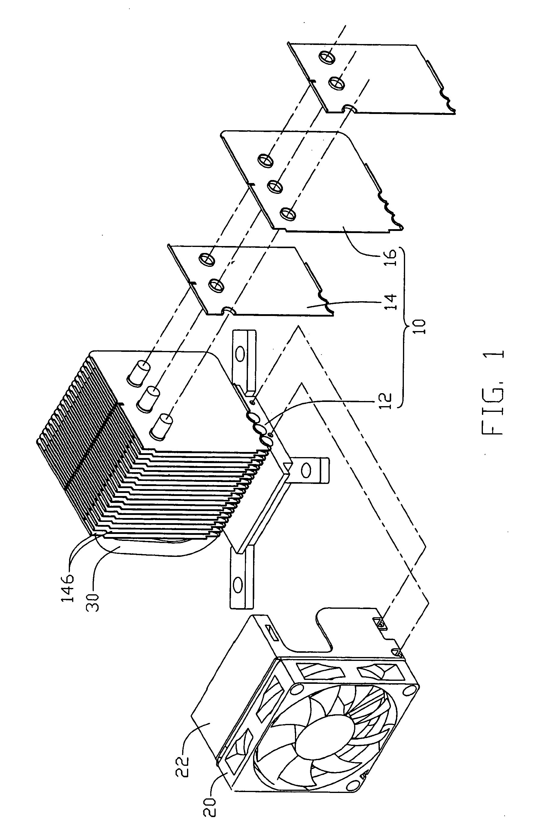
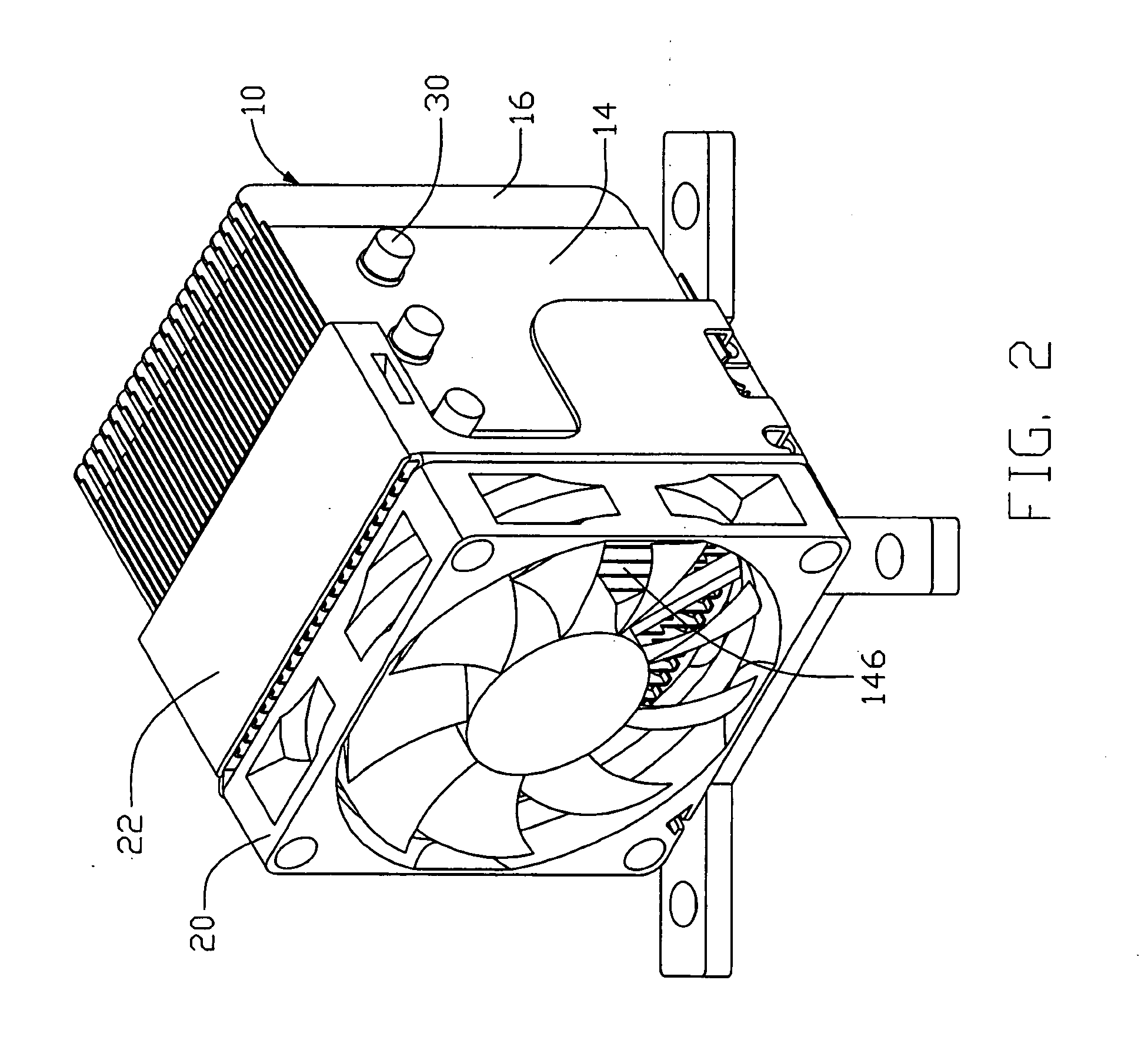
[0014] Referring to FIG. 1 and FIG. 2, a heat sink 10 of a heat dissipation device according to the present invention is shown. The heat sink 10 is secured on a heat source like a CPU (not shown) mounted on a printed circuit board (not shown). A fan 20 is fastened on a side of the heat sink 10 by a bracket 22. Three U-shape heat pipes 30 connect two opposite portions of the heat sink 10 by two parallel section thereof, for accelerating heat transfer from the portion close to the CPU to the other portion of the heat sink 10.

[0015] The heat sink 10 comprises a base 12 for contacting the CUP to absorb heat generated by it, and a plurality of parallel and spaced fins arranged on the base 12. The base 12 and the fins are made separately, and the fins are arranged on the base 12 by welding or adhering or other means. The fins comprise a plurality of first fins 14 and second fins 16. The first fins 14 are uniform with the second fins 16 in height, while the width of them is different. Such...

second embodiment

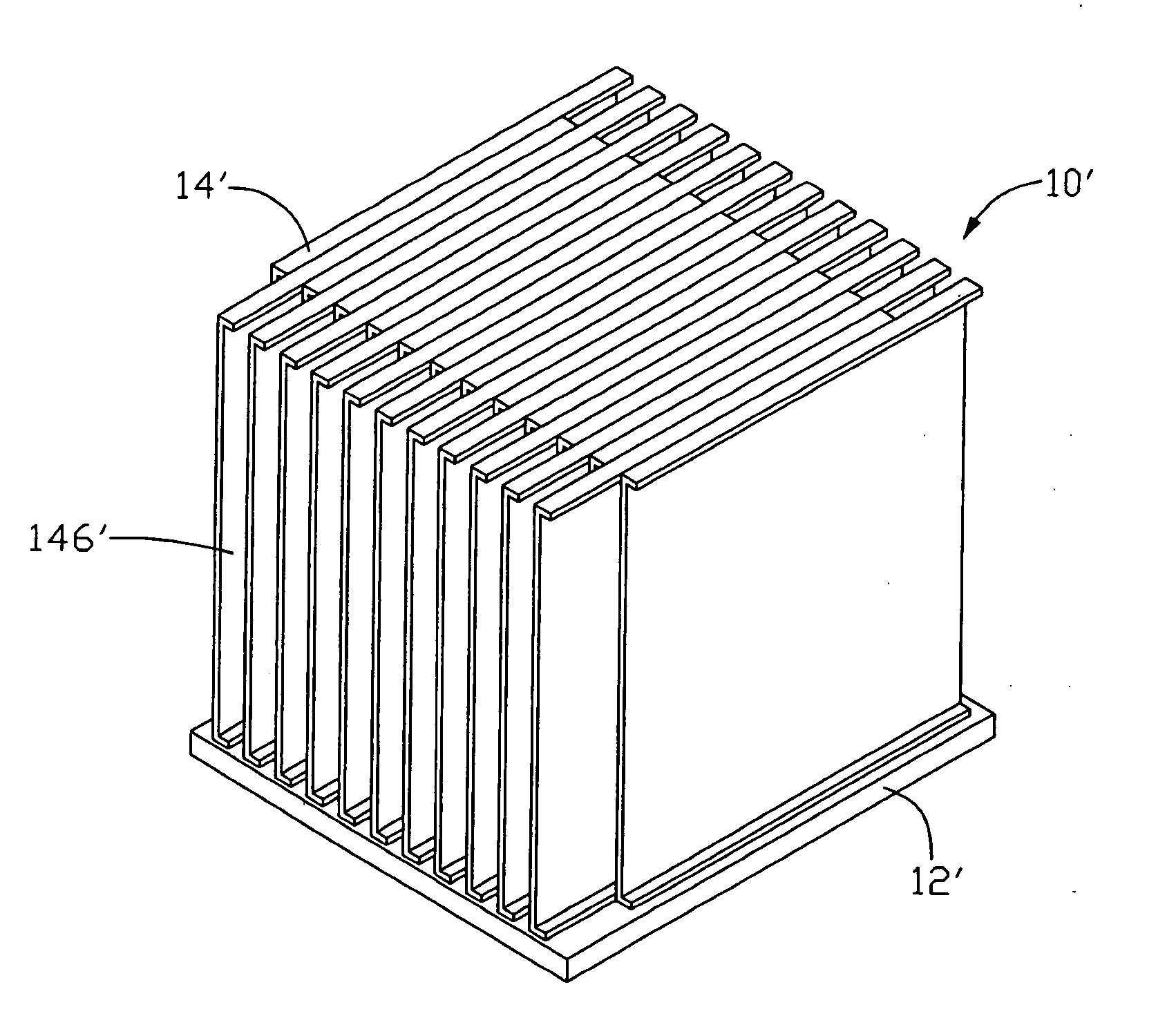
[0016] Referring to FIG. 3, a heat sink 10′ according to the present invention, comprises a plurality of parallel and uniform fins 14′ arranged on a base 12′. The adjacent fins 14′ are staggered with one another, such that one end of each fin 14′ project laterally beyond the adjacent one. Accordingly, an inlet and an outlet defined respectively at two opposite ports of each passage 146′ defined between the adjacent fins 14′, are wider than a middle part of the passage 146′.

third embodiment

[0017] Referring to FIG. 4, a heat sink 10″ according to the present invention, comprises a plurality of parallel fins attached on the base 12″. The fins comprise a plurality of first fins 14″ and second fins 16″. The first fin 14″ is different from the second fin 16″ in height and width. According to FIG. 4, both the height and width of the first fin 14″ are smaller than those of the second fin 16″. The first fins 14″ and second fins 16″ are disposed alternately. As a result, an upper end and two lateral ends of the second fins 16″ project beyond the first fins 14″.

[0018] According to the third embodiment of the present invention, as a replacement, the width of the first fin 14″ is smaller than that of the second fin 16″, while the height of the first fin 14″ is larger than that of the second fin 16″.

[0019] Referring to FIG. 5, a heat sink 10′″ according to a forth embodiment of the present invention, comprises a plurality of parallel fins arranged on the base 12′″. The fins compr...


PUM


Abstract

A heat sink includes a base and a plurality of spaced parallel fins arranged on the base. Adjacent fins define a plurality of passages there between. Each passage includes an inlet and at least one outlet. The base and the fins made separately, and the fins is thin, such that amount of the fins arranged on the base increases. And the fins are disposed on the base alternately or/and staggered such that the inlet and the outlet are wider than a middle part of the passage to lower airflow resistance thereat. Thus, the heat sink has large heat dissipating area and low airflow resistance synchronously.

Description

BACKGROUND [0001] 1. Field of the Invention [0002] The present invention relates generally to heat sinks, and more particularly to a heat sink used for heat generating electronic components. [0003] 2. Prior Art [0004] It is acknowledged that electronic components such as central processing units (CPUs) generate amounts of heat during operation. With advancement of computer technology, the ability of electronic components is upgraded rapidly. Accordingly, more and more heat is generated. In order to dissipate the heat generated by the electronic components, numerous heat dissipation devices are applied. Generally, a heat dissipation device comprises a heat sink. And in order to provide forced convection airflow to the heat sink, a fan is often attached to the heat sink. The heat sink comprises a first surface in close contact with the electronic component, for absorbing heat generated by the electronic component, and a second surface forming a plurality of spaced fins, for dissipatin...

Claims


Application Information

Patent Timeline
Patent Type & Authority Applications(United States)
IPC IPC(8): G06F1/20H01L23/34H01L23/367H01L23/467H05K7/20
CPCH01L23/3672H01L23/467H01L2924/0002H01L2924/00
Inventor CHEN, CHUN-CHIZHOU, SHI-WENWUNG, SHIN-HSUUWU, ZHAN
Owner HON HAI PRECISION IND CO LTD
Why Eureka
Try Eureka