Low-noise machine package

a machine package and low-noise technology, applied in the field of machine packages, can solve the problems of increasing airflow resistance, deteriorating cooling performance, increasing airflow resistance, etc., and achieve the effects of reducing noise, reducing airflow resistance, and minimizing the amount of cooled air

Inactive Publication Date: 2010-12-07
HITACHI IND EQUIP SYST CO LTD
View PDF19 Cites 17 Cited by
  • Summary
  • Abstract
  • Description
  • Claims
  • Application Information

AI Technical Summary

Benefits of technology

[0023]According to the present invention, noise reduction can be achieved while reducing the airflow resistance, thus making it possible to minimize a decrease in the amount of cooled air and improve the package heat radiation performance. Moreover, since enough heat radiation performance can be provided, a cooling fan can be downsized, which makes it possible to reduce noise generated from the cooling fan, reduce the fan power, and make the sound-absorbing structure even smaller, thus permitting achieving downsizing of the package.

Problems solved by technology

The conventional sound absorbing structure of a sound absorbing duct type requires space for noise in a band of 500 to 2 kHz which finds the widest applications, and thus faces problems concerned with costs, weight, etc. and also a problem of antinomy that an attempt to enhance the noise reduction performance increases the airflow resistance and then deteriorates the cooling performance.
The conventional duct lined with a sound absorbing member or, as its application, the cell-type and the splitter-type have many problems in practical aspects such as sound reducing performance, space, weight, costs, etc., since an attempt to increase the amount of sound reduction for a band of 500 to 2 kHz in highest need of sound reduction requires narrowing down the duct length, the thickness of the lined sound absorbing member, and the opening, which results in an increase in the airflow resistance.
H9-126666 and 2000-87725 has the cylindrical sound absorbing member arranged in such a manner as to intersect with airflow, and thus provides the effect of reducing the airflow resistance, but did not give sufficient consideration to sound absorbing properties concerning the material of the sound absorbing member with respect to the sound absorbing effect.
H9-26177 and 2002-266756 has the sound absorbing member arranged in parallel to airflow and thus has the same problem as the aforementioned cell-type and splitter-type have, and further does not give sufficient consideration to sound absorbing properties concerning the material of the sound absorbing member with respect to the sound absorbing effect.

Method used


Image

  • Low-noise machine package
  • Low-noise machine package
  • Low-noise machine package

Examples


second embodiment

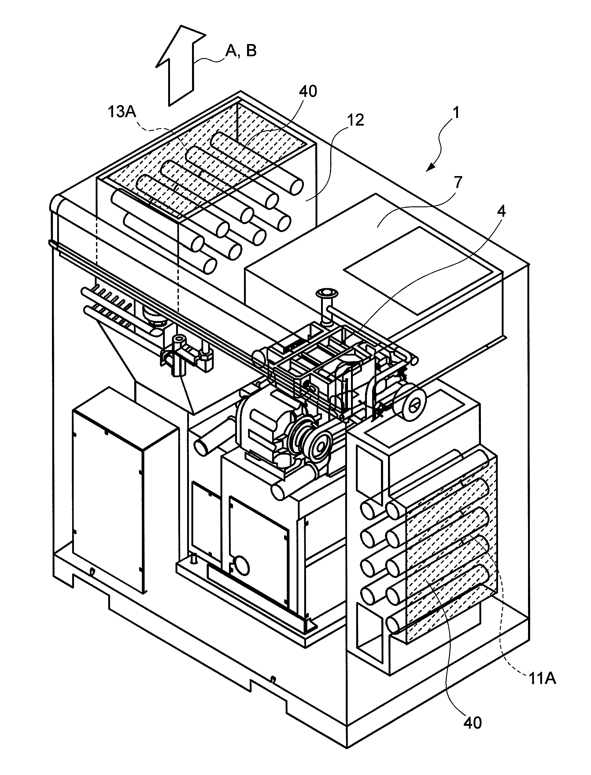
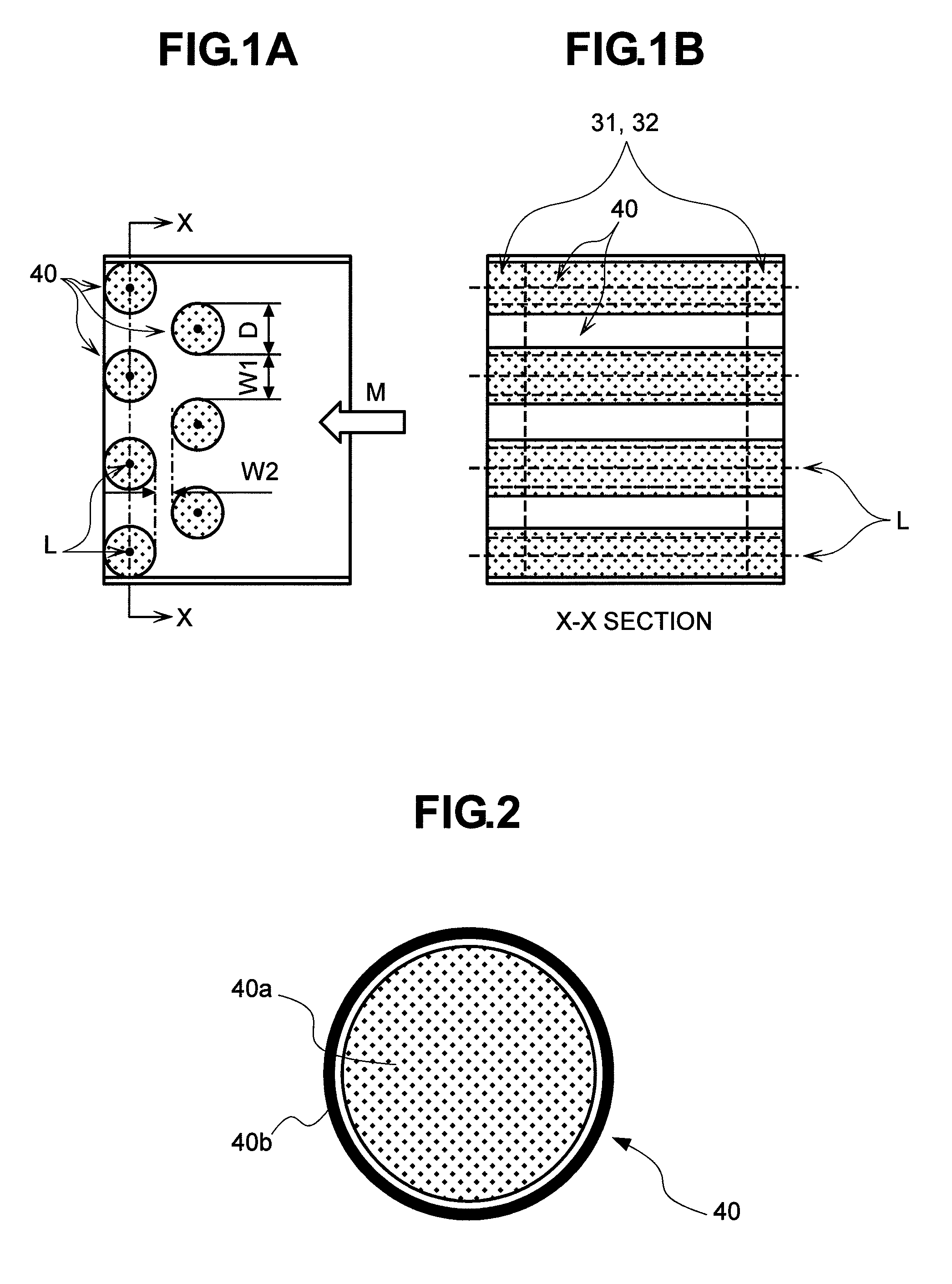
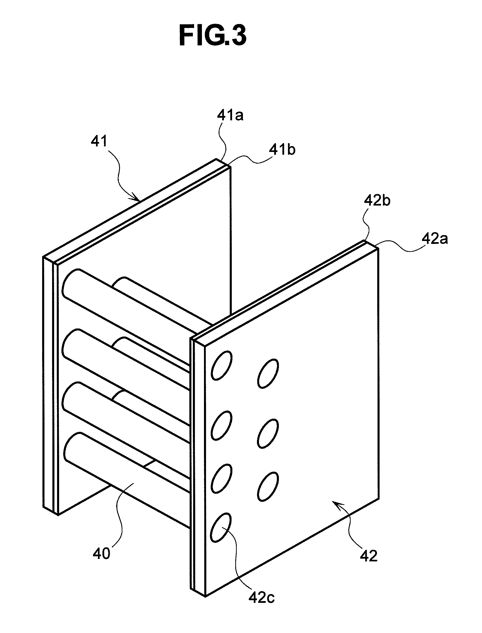
[0059]Next, the present invention will be described. In this embodiment, in addition to sound absorbing cylinders each formed of a base material of polyester fiber whose surface is combined with polyester-fiber-based nonwoven fabric, a support member supporting this sound absorbing cylinder is also structured to have sound absorbing effect. Specifically, as shown in FIG. 3, a polyester fiber sound absorbing member formed of a base material of polyester fiber whose surface is combined with polymer nonwoven fabric of polyester fiber or the like is provided with holes for supporting the sound absorbing cylinders and provided at the both ends of a package opening so that the sound absorbing cylinders are inserted therein. This structure achieves overall noise reduction. Other structure of an air compressor unit 1 to which a low-noise package of this embodiment is applied is the same as that of FIG. 12 and thus its description will be omitted here.

[0060]The structure for supporting the a...

first embodiment

[0065]Also in this embodiment, forming an array of sound absorbing cylinders 40 with sound absorbing members of a layered structure as described in the first embodiment can solve the difficulties in fitting due to an increase in the number of sound absorbing cylinders 40, thus considerably improving the operability.

[0066]As a method of fitting the sound absorbing cylinders 40 to the air compressor unit 1 in this embodiment, as described in the first embodiment, the sound absorbing cylinders 40 may be fixed directly to the suction port 11A and the exhaust port 13A, or may be provided in a freely detachable cassette form for easier maintenance. Also in this embodiment, providing the cassette structure has the advantage that it can be easily fitted as a module for noise reduction.

[0067]The model experiments and the evaluation described above demonstrate excellent performance of a low-noise package of this embodiment that solves the antinomy between the heat radiation performance and th...


PUM


Abstract

A conventional machine package faces problems concerned with costs, weight, etc. and also a problem of antinomy that an attempt to enhance the noise reducing performance increases the airflow resistance and then deteriorates the cooling performance. Providing a sound absorbing structure with the heat radiation performance ensured within a practical range and then with considerably improved noise reducing effect achieves a low-noise machine package with a downsized casing and a reduced cooling fan power. There is provided a sound absorbing structure having a plurality of polyester fiber sound absorbing cylinders each formed into a circular-cylindrical shape, formed of a base material of polyester fiber whose surface is combined and covered with polymer nonwoven fabric of polyester fiber or the like, and arranged at a support member in at least either of a suction port and an exhaust port in such a manner that long axes of the sound absorbing cylinders intersect substantially perpendicularly with a flow direction of air flowing through the suction port or the exhaust port. This makes it possible to reduce noise while controlling the airflow resistance minimum, thus achieving downsizing of a cooling fan and reduction of a cooling fan power.

Description

CLAIM OF PRIORITY[0001]The present application claims priority from Japanese application serial No. 2007-21594 filed on Jan. 31, 2007, the content of which is hereby incorporated by reference into this application.BACKGROUND OF THE INVENTION[0002]The present invention relates to a machine package having a sound absorbing structure for reducing noise radiated from an opening provided for cooling down heat generated from a machine, such as an industrial machine, having a suction port and an exhaust port.[0003]Most typically used as a conventional sound absorbing structure for an opening are: a lined duct using a porous material such as glass wool, a sprit type, a cell-type, etc., a basic form of each of which is a duct lined with a sound absorbing member.[0004]The duct lined with a sound absorbing member faces a decrease in the amount of sound reduction in a high sound area where the wavelength of sound is smaller than the diameter or short side of a cross section thereof since a soun...

Claims


Application Information

Patent Timeline
Patent Type & Authority Patents(United States)
IPC IPC(8): G10K11/04
CPCF01N1/10F01N2590/00F01N1/02F01N1/04
Inventor YABE, TOSHIAKISHIINOKI, KAZUAKIIIDA, KAZUYOSHIIKEDA, KOJI
Owner HITACHI IND EQUIP SYST CO LTD
Why Eureka
Try Eureka