Diffractive optical element and optical system including the same

a technology of optical elements and optical systems, applied in the field of diffractive optical elements, can solve the problems of low diffraction efficiency of envelope faces and decrease in diffraction efficiency for design orders, and achieve the effect of minimizing the decrease in diffraction efficiency

Active Publication Date: 2007-11-27
CANON KK
View PDF9 Cites 7 Cited by
  • Summary
  • Abstract
  • Description
  • Claims
  • Application Information

AI Technical Summary

Benefits of technology

[0029]The present invention provides a diffractive optical element that minimizes a decrease in diffraction efficiency even when a diffraction grating has an envelope face with a small radius of curvature. The present invention is also directed to an optical system incorporating the diffractive optical element.

Problems solved by technology

In the case where a light ray of a diffraction order different from a design order is present, the light ray is imaged at a location different from that for a light ray of the design order and thus results in flare.
The decrease in diffraction efficiency for the design order leads to diffraction rays of other orders and results in flare.
As a result, the structure in which the diffractive optical element is optimized for a pencil of light incident from the direction normal to the envelope face may have low diffraction efficiency.

Method used


Image

  • Diffractive optical element and optical system including the same
  • Diffractive optical element and optical system including the same
  • Diffractive optical element and optical system including the same

Examples


first embodiment

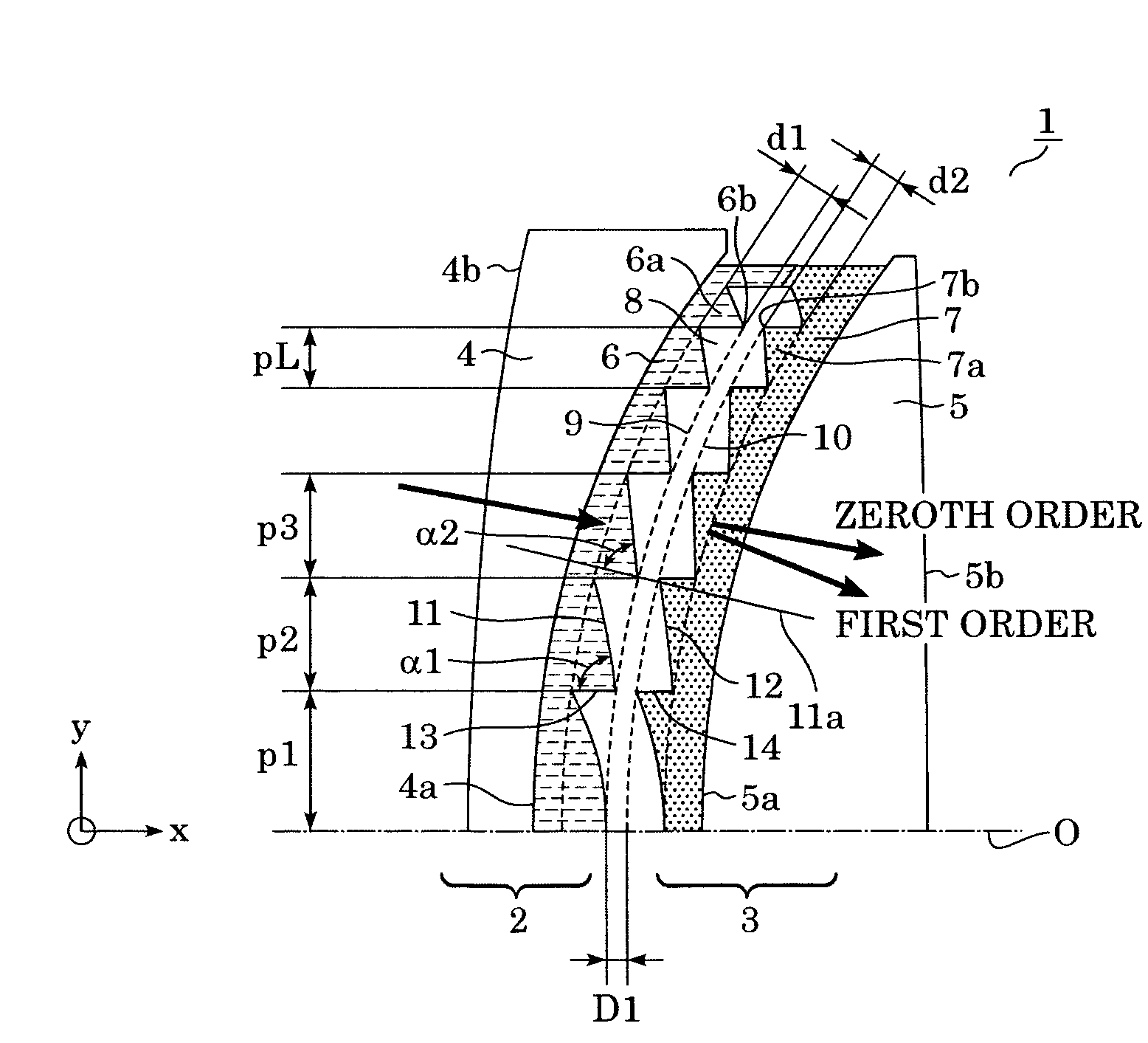
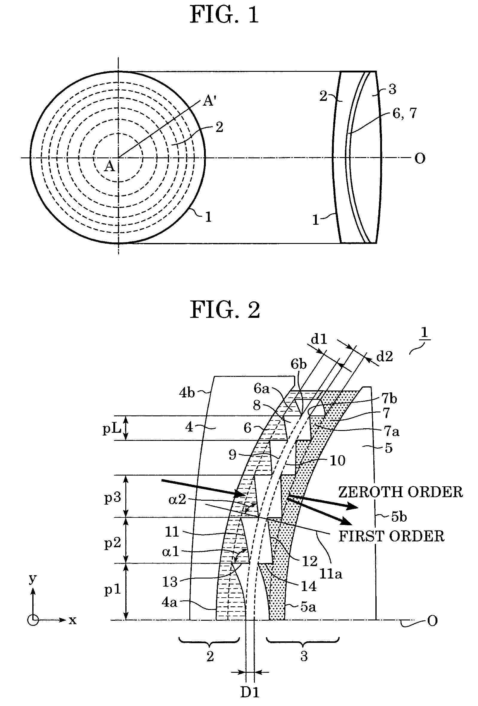
[0052]A diffractive optical element 1 according to a first embodiment of the present invention is described below. FIG. 1 is a schematic view (including a front view and a side view) of the diffractive optical element 1 according to the first embodiment. The diffractive optical element 1 includes a first diffraction part 2 and a second diffraction part 3 disposed adjacent to each other (layered) with a distance D1 therebetween.

[0053]In FIG. 1, a first diffraction grating 6 and a second diffraction grating 7 have concentric grating parts and have a lens function (convergent or divergent function). The first diffraction grating 6 and the second diffraction grating 7 are formed on curved faces.

[0054]FIG. 2 partly shows the diffractive optical element 1 in cross section taken along line A-A′ of FIG. 1. For the sake of clarity, FIG. 2 is not drawn to scale, especially in the direction of depth of the gratings, and the shown number of the grating part is lower than the actual number.

[0055...

second embodiment

[0111]In the first embodiment, the layered diffractive optical element has the two diffraction gratings disposed adjacent to each other with the air layer therebetween. The diffractive optical element in the present invention is not limited to this structure, and can be applied to a layered diffractive optical element 1 shown in FIG. 10.

[0112]In the structure shown in FIG. 10, a second diffraction grating, as in the first embodiment, is disposed such that a second grating surface is disposed at the boundary of two different materials. A third diffraction grating 16 is disposed in a part of an air layer 8 in the second embodiment. Therefore, a face 10a opposite to a grating face of the third diffraction grating 16 is a curved face having a curvature substantially the same as each of the first envelope face 9 and the second envelope face 10.

[0113]In this case, a second grating surface 12 has a larger radius of curvature than that of the second envelope face 10, as with the case of the...

third embodiment

[0114]In the first and second embodiments, the first diffraction grating 6 and the second diffraction grating 7 are adjacent to each other. This structure requires that the relative positions of the two diffraction gratings be accurately determined.

[0115]In a third embodiment, as shown in FIG. 11, a first diffraction grating 6 is bonded to a second diffraction grating 7 with a bonding layer 18 at a part where a grating part is not formed. If the assembly operation up to bonding is conducted in a clean room, adherence of dust particles to a first grating surface 11 and a second grating surface 12 is largely reduced.

[0116]In addition, after the first grating surface 11 and the second grating surface 12 are bonded together, an operator or the like does not touch the first grating surface 11 and the second grating surface 12. Therefore, the workability of incorporation of the diffractive optical element 1 into another optical system is greatly improved.


PUM


Abstract

A diffractive optical element includes a plurality of diffraction gratings. A diffraction grating within the plurality of diffraction gratings includes a plurality of grating parts having a curved grating surface and grating tips which connect to define a curved envelope face. The grating surface has a radius of curvature larger than a radius of curvature of the envelope face. In addition, two diffraction gratings within the plurality of diffraction gratings are composed of different materials having different dispersions. Therefore, even when the radius of curvature of the envelope face is small, the degradation of the diffraction efficiency is suppressed.

Description

BACKGROUND OF THE INVENTION[0001]1. Field of the Invention[0002]The present invention relates to diffractive optical elements, and in particular, to a diffractive optical element suitable for use with light having plural wavelengths or bandwidths and to an optical system including such diffractive optical element.[0003]2. Description of the Related Art[0004]In order to reduce chromatic aberration, in addition to a method of utilizing a combination of lenses of different glass materials, a method using a diffractive optical element disposed on a surface of a lens or arranged as part of an optical system is known. This diffractive method is disclosed in, for example, SPIE, vol. 1354, International Lens Design Conference, 1990; Japanese Patent Laid-Open No. 4-213421 (corresponding to U.S. Pat. No. 5,044,706); and Japanese Patent Laid-Open No. 6-324262 (corresponding to U.S. Pat. No. 5,790,321).[0005]This method utilizes a physical phenomenon in which chromatic aberration of a light ray...

Claims


Application Information

Patent Timeline
Patent Type & Authority Patents(United States)
IPC IPC(8): G02B5/18G02B27/42
CPCG02B5/1814G02B5/1866G02B5/1895G02B27/4277G02B27/42G02B27/4211G02B27/0037
Inventor NAKAI, TAKEHIKO
Owner CANON KK
Why Eureka
Try Eureka