
Reactor Feedwater Pump Control System

a technology of pump control and reactor feedwater, which is applied in the direction of machines/engines, positive displacement liquid engines, lighting and heating apparatus, etc., can solve the problems of short time period of output of the above-described decelerating operation instruction, the actual rotational speed of each reactor feedwater pump is limited, and the feedwater flow of feedwater supplied to the steam generator cannot be rapidly decreased. , to achieve the effect of suppressing the decrease in water level of the steam generator and minimizing th

Inactive Publication Date: 2012-07-19
HITACHI LTD
View PDF8 Cites 11 Cited by
  • Summary
  • Abstract
  • Description
  • Claims
  • Application Information

AI Technical Summary

Benefits of technology

[0016]The present invention has been made on the basis of the foregoing facts and circumstances. An object of the present invention is to provide a reactor feedwater pump control system such that, when a condensate pump trips, minimizes the decrease in feedwater flow supplied to a steam generator so as to suppress the water level decrease in the steam generator, and also prevents continuously operating condensate pumps from continuing run out operation.
[0036]According to the present invention, when a condensate pump is tripped, the decrease in feedwater flow of feedwater supplied to the steam generator can be minimized to suppress the decrease in water level of the steam generator. At the same time, operating condensate pumps can be prevented from continuing a run out operation.

Problems solved by technology

(1) Because of the characteristics of the ASDs, the rotational speed of the reactor feedwater pumps cannot be rapidly decreased. Therefore, even though the decelerating operation instruction is received, the actual rotational speed of each reactor feedwater pump decreases at a limited rate.
(2) A standby condensate pump is usually started shortly after one condensate pump is tripped. A start-up of the standby pump is determined by a closed contact signal of a power breaker. Thus, a time period of the output of the above-described decelerating operation instruction is short. After the standby pump is started, an accelerating operation instruction is output to return the flow to a normal rate.

Method used


Image

  • Reactor Feedwater Pump Control System
  • Reactor Feedwater Pump Control System
  • Reactor Feedwater Pump Control System

Examples


first embodiment

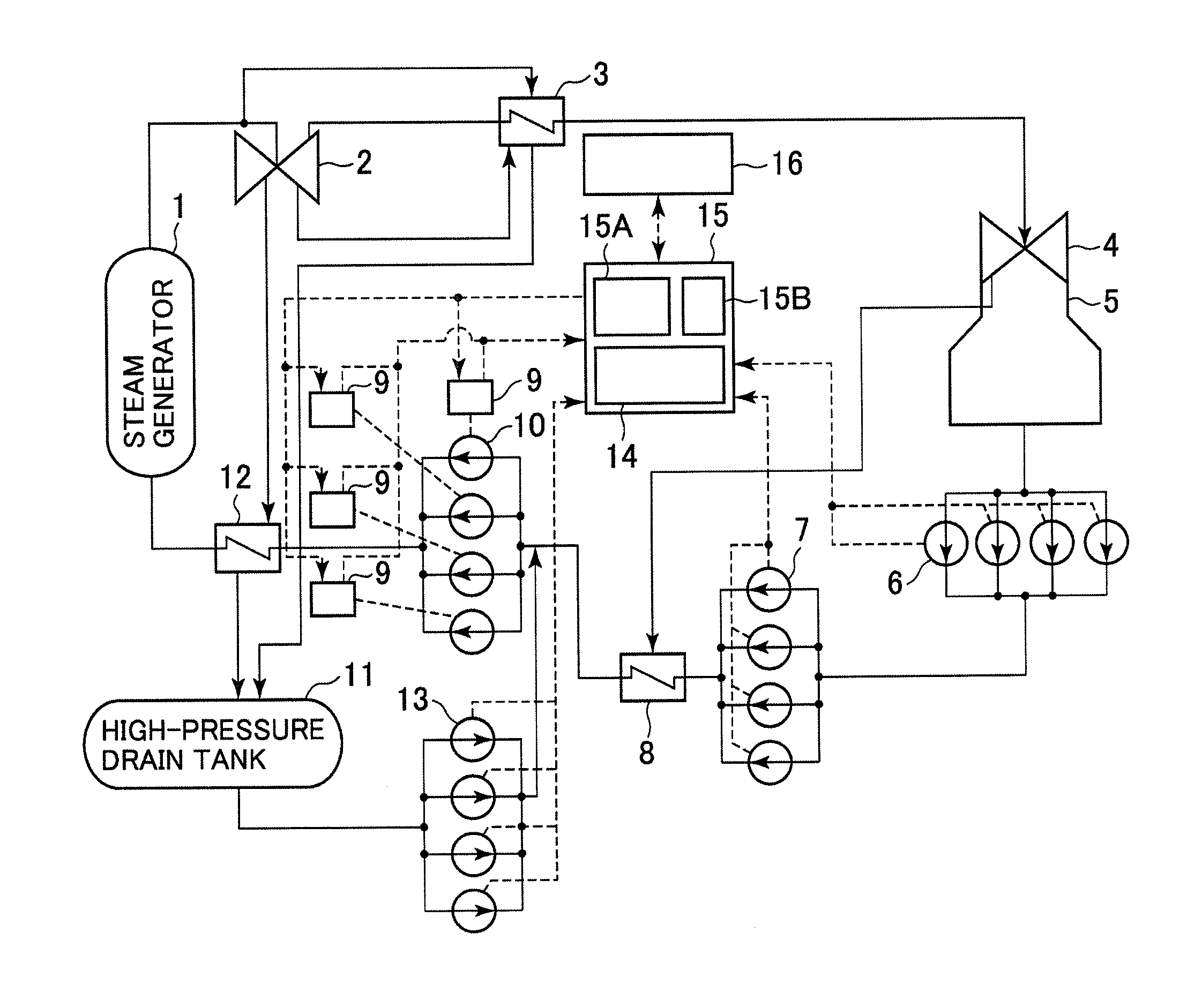
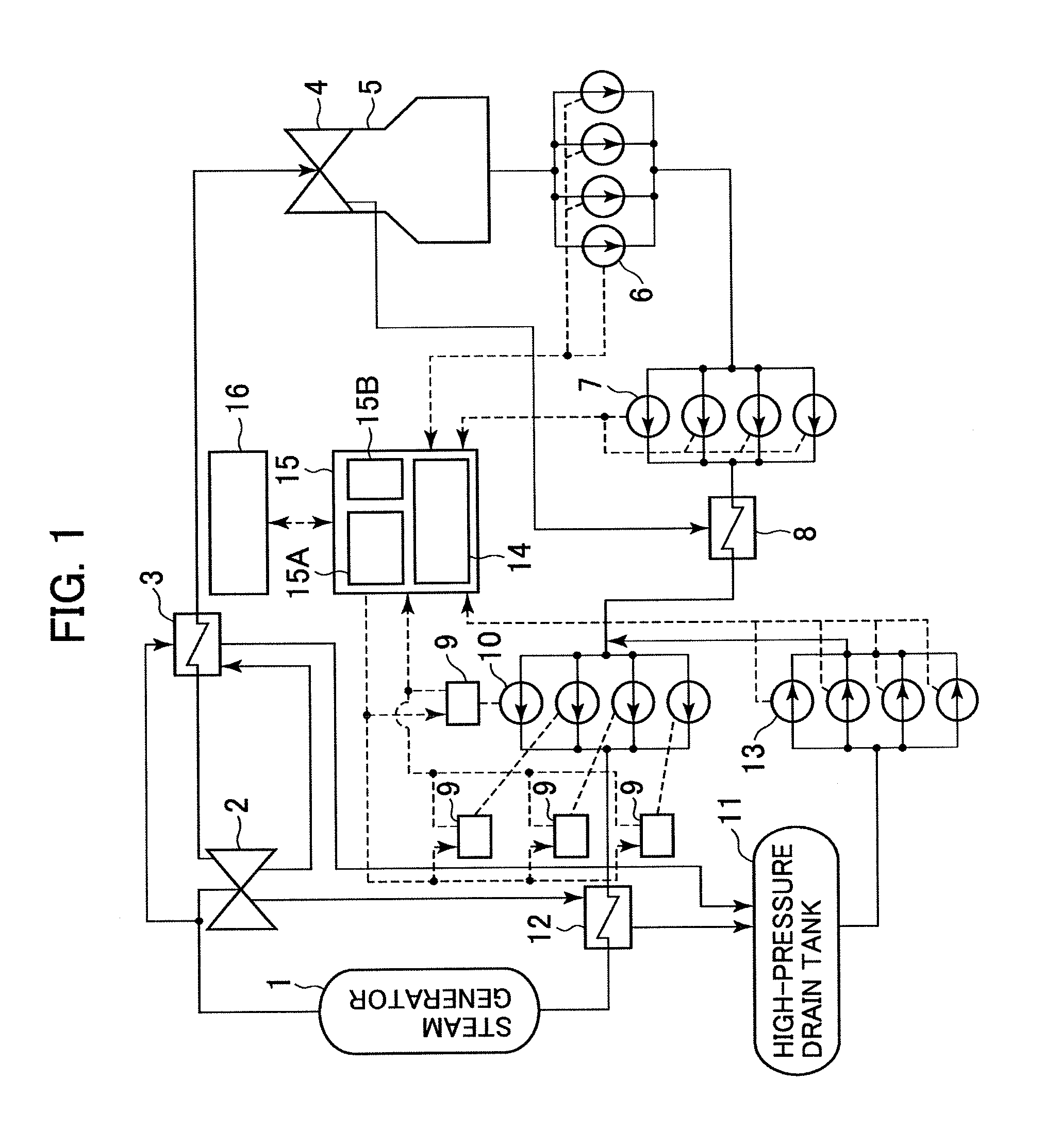
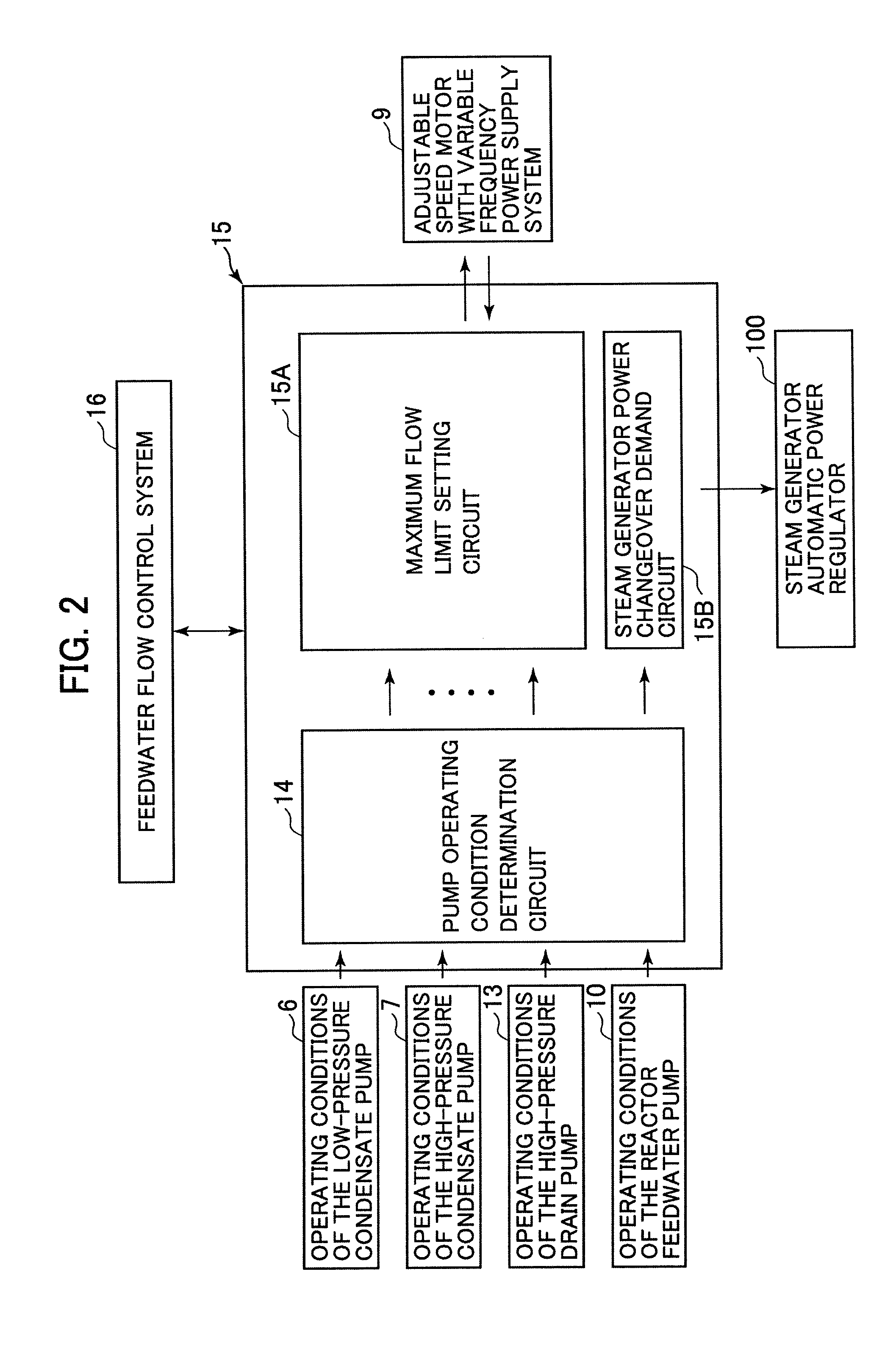
[0045]FIG. 1 is a systematic diagram illustrating a steam turbine facility to which a first embodiment of the reactor feedwater pump control system of the present invention is applied. FIG. 2 is a block diagram illustrating a configuration of the reactor feedwater pump control system according to the first embodiment of the present invention. FIG. 3 is a characteristic chart illustrating the operation during start-up of a standby condensate pump for tripping in the first embodiment of the reactor feedwater pump control system of the present invention.

[0046]In FIG. 1, steam generated by a steam generator 1 is supplied to a high-pressure turbine 2 through a supply pipe. The steam expanded by the high-pressure turbine 2 is passed through a steam pipe to a moisture separator reheater 3. The moisture separator reheater 3 reheats the steam and then supplies the reheated steam to a low-pressure turbine 4. The steam expanded by the low-pressure turbine 4 is condensed by a condenser 5 so as ...

second embodiment

[0064]A second embodiment of the reactor feedwater pump control system of the present invention will be described below with reference to the accompanying drawings. FIG. 4 is a characteristic chart illustrating the operation where a standby pump does not start up even required upon tripping of a condensate pump in the second embodiment of the reactor feedwater pump control system of the present invention. In the description referring to FIG. 4, reference numerals that are same as those shown in FIGS. 1 to 3 represent similar parts. Therefore the detailed description thereof will be omitted.

[0065]In the first embodiment, it was assumed that a standby pump started up when one of the plurality of low-pressure condensate pumps 6 tripped. Meanwhile in this embodiment, it is assumed that the standby pump would not start up even when one of the plurality of low-pressure condensate pumps 6 is tripped. The turbine facility, the reactor feedwater pump control system 15 and the like are config...

third embodiment

[0070]A third embodiment of the reactor feedwater pump control system of the present invention will be described below with reference to the accompanying drawings. FIG. 5 is a characteristic chart illustrating the operation where a standby pump would not start up even when a condensate pump is tripped in the third embodiment of the reactor feedwater pump control system of the present invention. In the description referring to FIG. 5, reference numerals that are same to those shown in FIGS. 1 to 4 represent similar parts. Therefore the detailed description thereof will be omitted.

[0071]The second embodiment discloses the example in which the standby pump would not start up even when one of the plurality of low-pressure condensate pumps 6 is tripped. This embodiment discloses another example of the operation in which the standby pump would not start as well. The turbine facility, the reactor feedwater pump control system 15 and the like are configured similarly to those disclosed in t...


PUM


Abstract

An object of the present invention is to provide a reactor feedwater pump control system, wherein when a condensate pump is tripped, the decrease in feedwater flow of feedwater supplied to a steam generator is minimized to suppress the decrease in water level of the steam generator, and at the same time preventing operating condensate pumps from continuing a run out operation. The feedwater pump control system is provided with a feedwater supply system, which includes a plurality of condensate pumps disposed in parallel for boosting condensate water from a condenser; a plurality of reactor feedwater pumps disposed in parallel for further boosting and supplying the condensate water to a steam generator; and variable frequency power supply systems each for driving an electric motor of the reactor feedwater pump at an adjustable speed.

Description

BACKGROUND OF THE INVENTION[0001]1. Field of the Invention[0002]The present invention relates to reactor feedwater pump control systems used in thermal power plants and reactor power plants.[0003]2. Description of the Related Art[0004]Generally, in a reactor power plant or a thermal power plant, steam generated by a nuclear reactor or a boiler as a steam generator is used to drive a steam turbine. After driving the steam turbine, the steam is cooled by a condenser to be used as condensate water. The condensate water is boosted by a feedwater supply system, and is then supplied to the steam generator. The feedwater supply system includes a plurality of condensate pumps and a plurality of reactor feedwater pumps both including a standby pump.[0005]When one of the condensate pumps on an upstream side of such a feedwater supply system trips, the flow output from the condensate pumps decreases. In such case, if reactor feedwater pumps on the downstream side are operated normally, balance...

Claims


Application Information

Patent Timeline
IPC IPC(8): F04B49/06F04B23/04
CPCF01K7/22F22D11/02F22B1/023
Inventor IGARASHI, KINGO
Owner HITACHI LTD
Learn More