
Method and system for utilization a fluctuated wind

a wind turbine and fluctuation wind technology, applied in the direction of mechanical equipment, machines/engines, electric generator control, etc., can solve the problems of limitation of kinetic energy and addition of wind power plants, and achieve the effects of reducing the cost and weight of wind power plants, and increasing the rotational speed of wind power plants

Inactive Publication Date: 2014-04-17
GRINBLAT ZINOVY D
View PDF8 Cites 10 Cited by
  • Summary
  • Abstract
  • Description
  • Claims
  • Application Information

AI Technical Summary

Benefits of technology

The present invention provides a method for eliminating the average mechanical power on the shaft of a wind turbine by using the weight of the turbine as a fly-will. The weight of the turbine is converted into kinetic energy during rotation and stored as mechanical power. The stored mechanical power needs to be compensated for losses caused by wind shear and blade pass through a tower. The present invention also provides a method for permanently keeping a high rectified variable DC voltage at the capacitor. This helps in addressing the future problem associated with fossil fuel. The use of one or two-blade wind turbine helps reduce the cost and weight of the wind turbine system and increases the rotational speed of wind turbines. The control system permits efficient utilization of wind energy by extracting maximum mechanical power, producing and consuming the variable electrical power, and increasing the operating time.

Problems solved by technology

The disadvantage of keeping stability of the current wind conversion system and the ability to feed the connected greed with constant parameters is an additional cost of the wind power plant and limitation to kinetic energy drawn from the always fluctuating wind.

Method used


Image

  • Method and system for utilization a fluctuated wind
  • Method and system for utilization a fluctuated wind
  • Method and system for utilization a fluctuated wind

Examples


Embodiment Construction

[0051]The present invention provides the method of direct conversion the always fluctuating wind energy into variable electrical power, consuming its variable electrical power with accordance of the equation (1) and wind conversion system based thereon method.

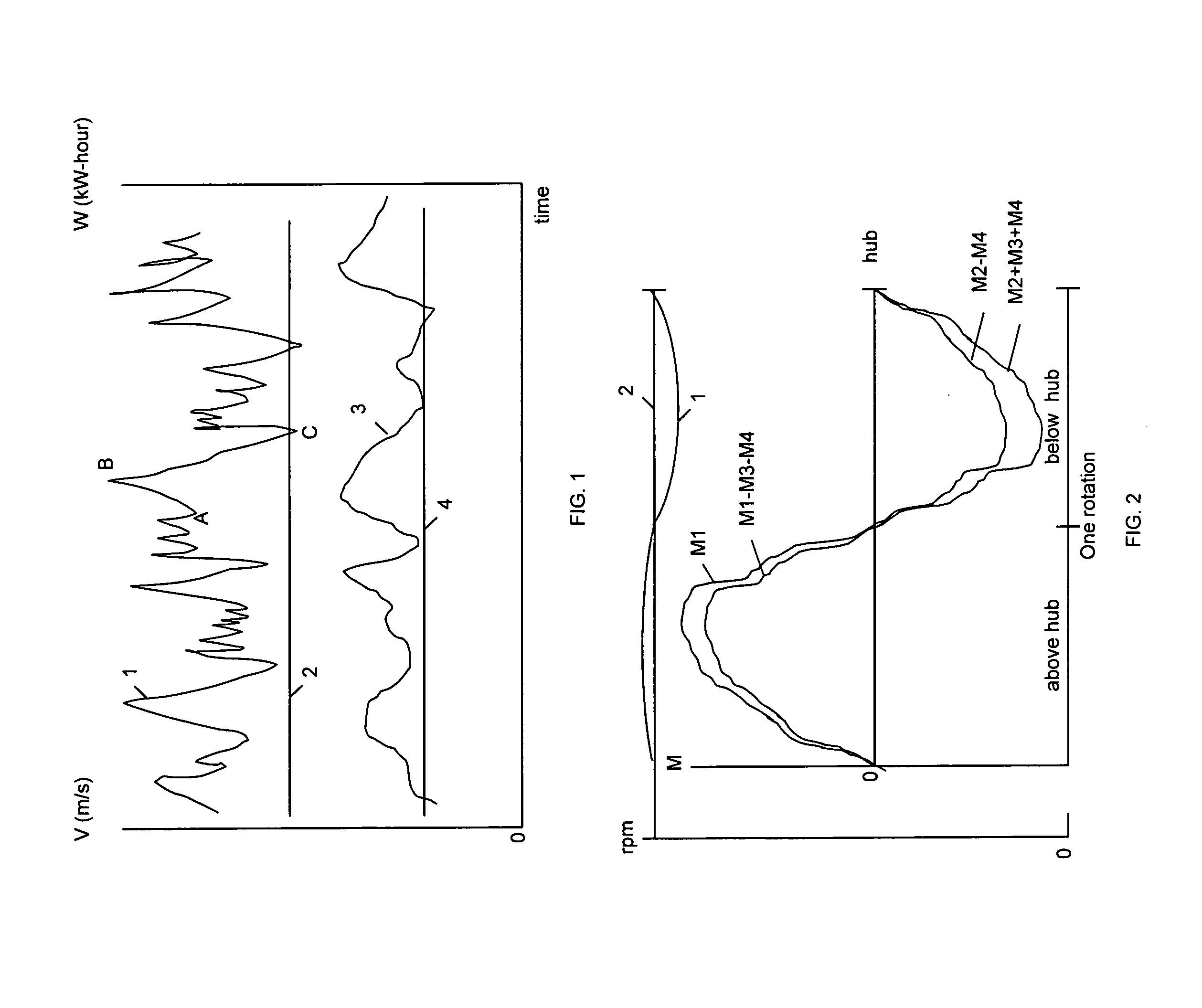
[0052]FIG. 1 illustrates a fluctuated wind speed and kinetic wind energy. In the present drawing graph 1 represents fluctuated wind speed and graph 3 represents fluctuated wind kinetic energy. Wherein, graph 1 above and below line 2 represents dynamic and static part of wind speeds; graph 3 above and below line 4 represents dynamic and static part of wind kinetic energies; curve (A-B) represents positive slope (increasing wind speed); curve (B-C) represents negative slope (decreasing wind speed).

[0053]FIG. 2 illustrates a basic of current and present methods of extraction mechanical power from the wind. The current method of extraction mechanical power from the wind is the indirect conversion wind kinetic energy into the averag...


PUM


Abstract

The present method and system provides: conversion of always fluctuating wind into a variable AC electrical power P through wind turbine and electrical generator; consuming its variable AC power with accordance of an equation P−Pc−Pv=0; conversion of the variable AC power is drawing from two phases of an electrical generator into an AC power connected to an electrical grid through an six-pulls diode rectifier, first heat energy exchanger, DC capacitor and DC-AC inverter; conversion a variable AC power drawing from third phase of an electrical generator into heat through switches connected to a neutral line or into a constant voltage DC power through an six-pulls bridge rectifier, second heat energy exchanger and DC capacitor; permanently keeping the rectified variable DC voltage is higher than a DC constant voltage at the buffer capacitor.

Description

[0001]United States patent7,015,595September 2006 Feddersen, et al.7,075,189July 2006 Heronemus, et al.7,233,079June 2007 Cooper7,579,702September 2009 Park, et al.7,748,958July 2010 McVeigh, et al.7,922,449April 2011 Scholte-Wassink8,207,624June 2012Gonzales20030223868December 2003Dawson, Mark H., et al.20080317600December 2008Enevoldsen; Peder Bay; et al.20090047116February 2009Barbu; Corneliu; et al.REFERENCES CITED[0002][1] D. Berry et al., “Parametric study for large wind turbine blades”[0003][2] G. Gail, et al., “Controller design and analysis of a variable speed wind turbine with doubly-fed induction generator”[0004][3] M. Schmidt, “Wind turbine design optimization”[0005][4] M. Hansen, “Aerodynamics of wind turbines”[0006][5] E. Hau, “Wind turbine fundamentals, technologies, application, economics”[0007][6] J. Manwell, et al., “Wind energy explained theory, design and application”[0008][7] G. Shrestla, et al., “Direct drive wind turbine generator with magnetic bearing”[0009][...

Claims


Application Information

Patent Timeline
Patent Type & Authority Applications(United States)
IPC IPC(8): H02P9/04
CPCF03D7/0272H02P9/48H02P2101/15Y02E10/72
Inventor GRINBLAT, ZINOVY D.
Owner GRINBLAT ZINOVY D
Learn More