Optical integrated unit and optical pickup

a technology of optical pickup and integrated unit, which is applied in the field of optical integrated unit and optical pickup, can solve the problems of conventional optical integrated unit suffering, loss of light amount, and inability to form a fine spot of laser beam on the optical disk, and achieve the effect of minimizing the decrease of light utilization efficiency and recording/reproducing performan

Inactive Publication Date: 2006-12-07
SHARP KK
View PDF7 Cites 10 Cited by
  • Summary
  • Abstract
  • Description
  • Claims
  • Application Information

AI Technical Summary

Benefits of technology

[0015] The present invention is made in light of the problems, and its object is to provide an optical integrated unit and an optical pickup, each of which allows more stable recording / reproducing performance by correcting the intensity of light, emitted from a light source, so as to minimize decrease of light utilization efficiency.
[0019] In other words, the above structure is a structure, which uses the polarization light and which includes (i) the diffracting means for diffracting the first polarization component light in the direction toward the optical information recording medium, and for diffracting the second polarization component light in the direction toward the light receiving element; and (ii) polarization component converting means for converting the returning light into the second polarization component light. This allows the light receiving element to efficiently receive the returning light coming from the optical information recording medium. Therefore, according to the above structure, the light beam diffracted by the diffracting means in the direction toward the optical information recording medium can be wholly used for detection of a signal, with the result that the light utilization efficiency becomes very high.
[0020] Therefore, the above structure makes it possible to provide an optical pickup, which does not need to use, e.g., a semiconductor laser having a strong power in cases where the light source is a semiconductor laser, and which costs low, and which has a stable recording / reproducing performance.
[0021] Further, the diffracting means diffracts the first polarization component light in the direction toward the optical information recording medium such that the decrease of the light intensity of the light beam is smaller as further from the vicinity of the optical axis of the light beam to the peripheral portion thereof. On this account, the light intensity distribution of the first polarization component light thus diffracted by the diffracting element in the direction toward the optical information recording medium is so corrected as to be closer to a flat light intensity distribution, and then the first polarization component light is collected on the optical information recording medium. This makes it possible to form a finer spot of the light beam on the optical information recording medium, with the result that the temporal resolution with respect to a reproduction signal is improved and the S / N ratio of the reproduction signal is improved.
[0022] As described above, the above structure makes it possible to provide an optical pickup which minimizes decrease of the light utilization efficiency by correcting the intensity of the light beam emitted from the light source.
[0024] This allows minimization of decrease of the light utilization efficiency, with the result that the optical pickup of the present invention is allowed to have more stable recording / reproducing performance.

Problems solved by technology

This makes it impossible to form a fine spot of the laser beam on the optical disk.
However, such a conventional optical integrated unit suffers from the following problems.
Upon the dividing, the light diffraction phenomenon causes decrease of the light intensity of each of the three light beams, with the result that light amount loss occurs.
Thus, light amount loss also occurs in this case.
This is one reason for the decrease of the light utilization efficiency.
This causes further decrease of the light utilization efficiency.
However, the strengthening of the power of the semiconductor laser causes short durability of the semiconductor laser.

Method used


Image

  • Optical integrated unit and optical pickup
  • Optical integrated unit and optical pickup
  • Optical integrated unit and optical pickup

Examples


embodiment 1

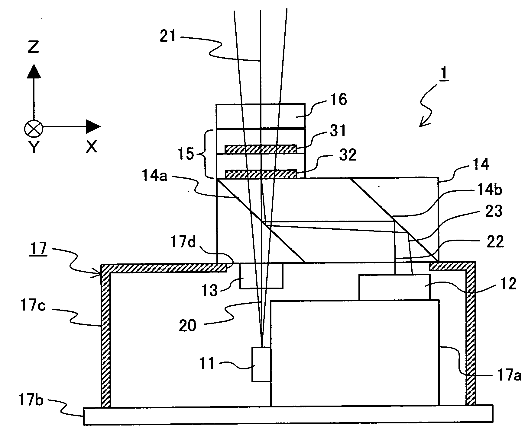
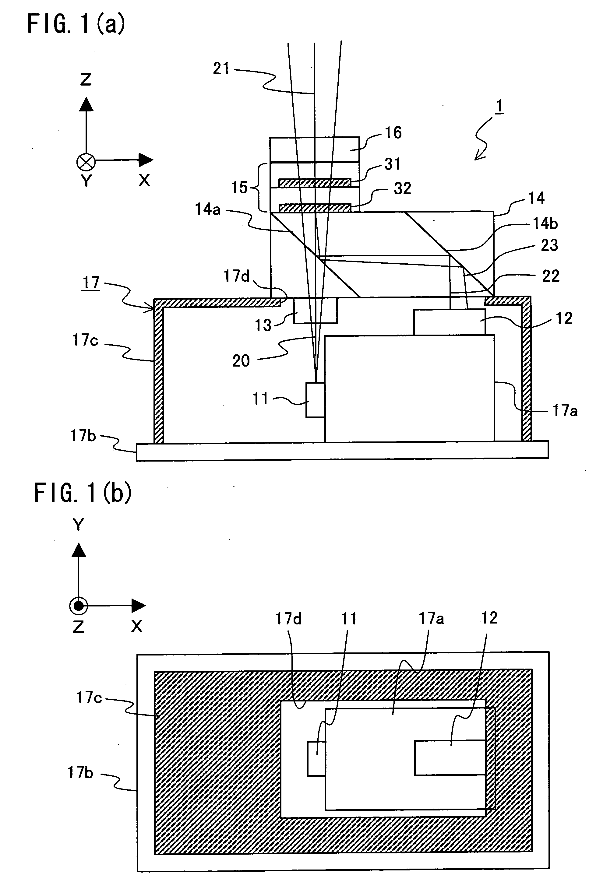
[0050] One embodiment of the present invention will be described below with reference to FIGS. 1(a) and 1(b) through FIGS. 7(a) and 7(b).

[0051] The present embodiment assumes a case where an optical integrated unit of the present invention is used in an optical pickup provided in an optical information recording / reproducing apparatus for optically recording and reproducing information onto and from an optical disk (optical information recording medium).

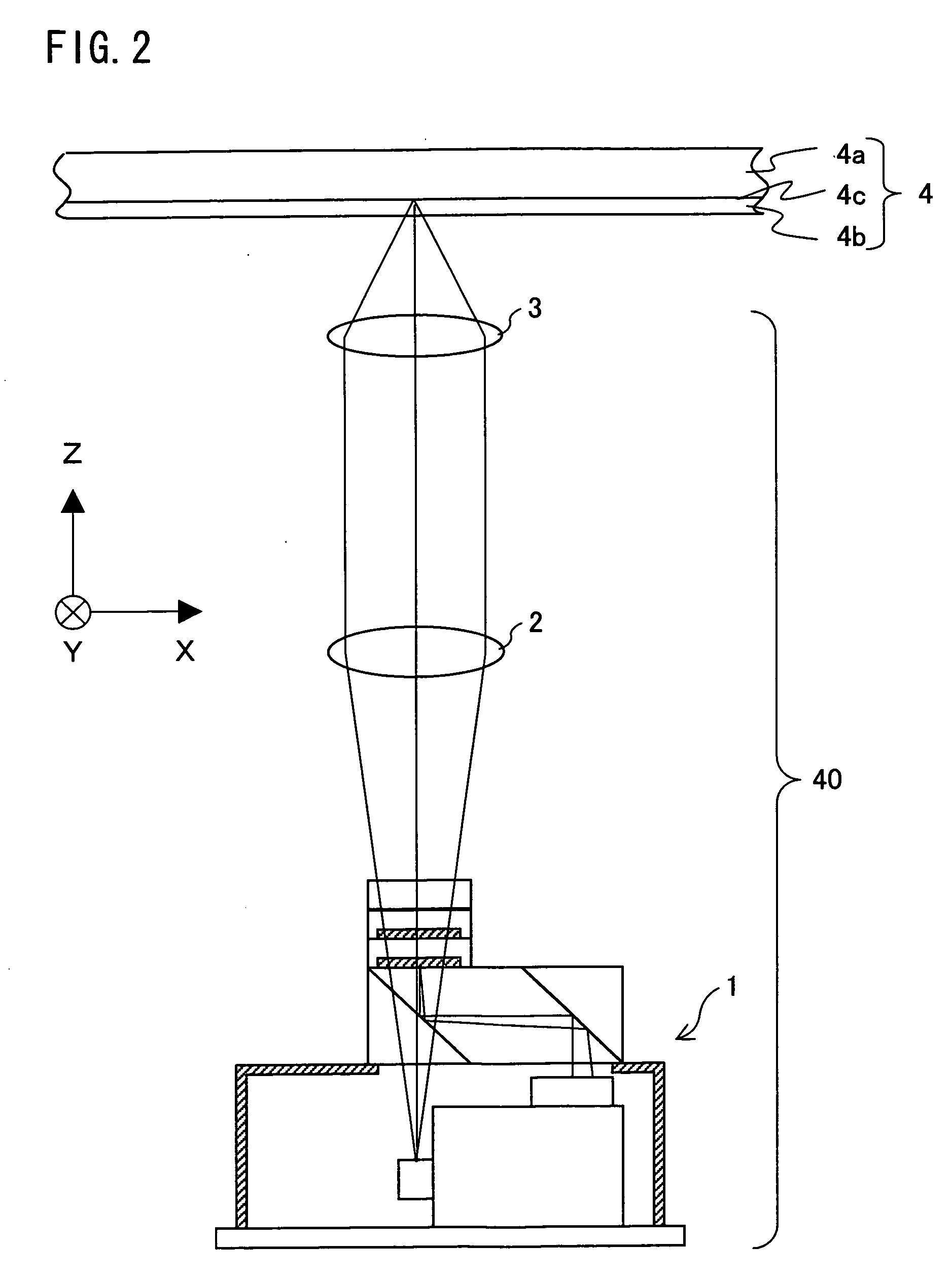
[0052]FIG. 2 is a diagram schematically illustrating a structure of an optical pickup 40 using an optical integrated unit of the present embodiment.

[0053] As shown in FIG. 2, the optical pickup 40 includes the optical integrated unit 1, a collimator lens 2, and an objective lens 3.

[0054] In FIG. 2, a light beam emitted from a light source provided in the optical integrated unit 1 is caused to be parallel light beams by the collimator lens 2, and then the parallel light beams are collected on an optical disk 4 by the objective lens...

embodiment 2

[0137] The following description deals with another embodiment of the present invention with reference to FIG. 8(a) and FIG. 8(b). Explained in the present embodiment are differences from Embodiment 1. Therefore, for ease of explanation, materials having the equivalent functions as those shown in the drawings pertaining to Embodiment 1 will be given the same reference symbols, and explanation thereof will be omitted here.

[0138] Each of FIG. 8(a) and FIG. 8(b) is a diagram schematically illustrating a structure of an optical integrated unit of Embodiment 2 of the present invention. FIG. 8(a) is a side view illustrating the optical integrated unit when viewed in the Y direction under conditions that the optical direction is considered as the Z direction shown in FIG. 8(a). FIG. 8(b) is an overhead view illustrating the optical integrated unit when viewed in the optical axis direction (Z direction) shown in FIG. 8(a), i.e., when viewed from the side of the window portion 17d of the ca...

embodiment 3

[0150] The following description deals with still another embodiment of the present invention with reference to FIG. 10. Explained in the present embodiment are differences from Embodiment 1. Therefore, for ease of explanation, materials having the equivalent functions as those shown in the drawings pertaining to Embodiment 1 will be given the same reference symbols, and explanation thereof will be omitted here.

[0151]FIG. 10 is a side view illustrating an optical integrated unit of Embodiment 3 of the present invention when viewed in the Y direction under conditions that the optical direction is considered as the Z direction illustrated in FIG. 10. The optical integrated unit of the present embodiment is different from the optical integrated unit of Embodiment 1 in terms of respective structures of the semiconductor laser 11 and the light receiving element 12.

[0152] Specifically, in Embodiment 1, the semiconductor laser 11 and the light receiving element 12 are provided in the pac...


PUM


Abstract

In order to realize a more stable recording / reproducing performance by minimizing decrease of light utilization efficiency, an optical integrated unit 1 of the present invention includes: (i) a semiconductor laser 11 for emitting a light beam 20 to an optical disk 4; (ii) a light receiving element 12 for receiving returning light, which is the light beam 20 reflected by the optical disk 4; (iii) a transparent element 15 for diffracting P polarization component light of the light beam 20 in a direction toward the optical disk 4, and for diffracting S polarization component light of the returning light in a direction toward the light receiving element; and (iv) a ¼ wavelength plate 16 that is provided on a portion, through which the returning light enters the transparent element 15, of the transparent element 15, and that converts the returning light into the S polarization component light.

Description

[0001] This Nonprovisional application claims priority under 35 U.S.C. § 119(a) on Patent Application No. 2005 / 130561 filed in Japan on Apr. 27, 2005, the entire contents of which are hereby incorporated by reference. FIELD OF THE INVENTION [0002] The present invention relates to an optical integrated unit and an optical pickup. More specifically, the present invention relates to (i) an optical integrated unit allowing realization of downsizing of an optical pickup for use in recording information onto or reproducing information from and optical information recording medium such as an optical disk, and (ii) an optical pickup including the optical integrated unit. BACKGROUND OF THE INVENTION [0003] Strongly demanded in recent years are (i) higher density and larger information recording capacity in an optical information recording medium such as an optical disk for the sake of storing a large amount of information, and (ii) downsizing and weight saving of an optical pickup for the sa...

Claims


Application Information

Patent Timeline
Patent Type & Authority Applications(United States)
IPC IPC(8): G02B5/18
CPCG02B5/32G11B7/0943G11B7/1205G11B7/13925G11B7/1353G11B7/1365G11B7/1369G11B7/131G11B7/123
Inventor KANAZAWA, YASUNORIHORIYAMA, MAKOTO
Owner SHARP KK
Why Eureka
Try Eureka