Vent duct

a technology of ventilation ducts and vents, applied in the direction of heating types, lighting and heating apparatus, bends, etc., can solve the problem of reducing ventilation resistance further without enlarge, and achieve the effect of reducing air-flow resistan

Inactive Publication Date: 2013-09-26
ROKI CO LTD
View PDF6 Cites 16 Cited by
  • Summary
  • Abstract
  • Description
  • Claims
  • Application Information

AI Technical Summary

Benefits of technology

[0008]The present invention was conceived in consideration of the circumstances mentioned above and an object thereof is to provide a vent duct capable of further reducing ventilation fluid-flow resistance without increasing size or dimension of the vent duct.
[0018]According to the present invention of the structures and characters mentioned above, since the protruded portion includes an upstream side end portion formed to be gently continuous to the inner peripheral surface portion of a downstream side portion of the bent portion, a body portion extending from the upstream side end portion toward the downstream side portion along the fluid flow passage, and a perpendicular portion formed at the downstream side end portion along the fluid flow passage to be continuous to the body, the vent duct can attain preferred function of reducing air-flow resistance without being enlarged in size or dimension.

Problems solved by technology

According to the structure of the conventional vent duct mentioned above, although the guide block has a semi-circular cross section, because of tendency of compact structure of an engine room of an automobile or location of various kinds of auxiliary components or parts, there has been caused constriction or restriction to free layout of the vent duct, and accordingly, it has been required to further reduce ventilation resistance without making enlarge the structure or configuration of the vent duct.

Method used


Image

  • Vent duct
  • Vent duct
  • Vent duct

Examples


first embodiment

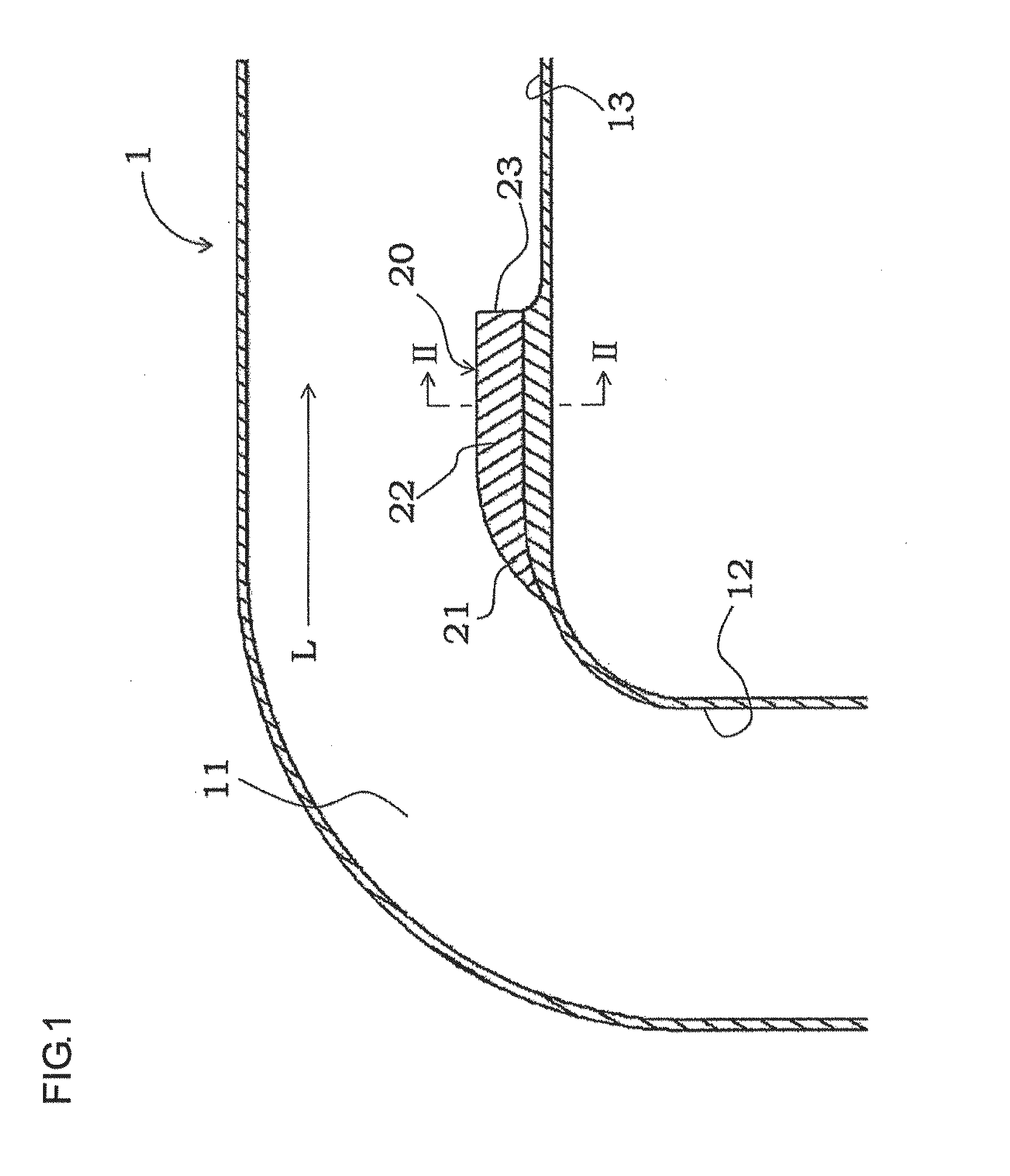
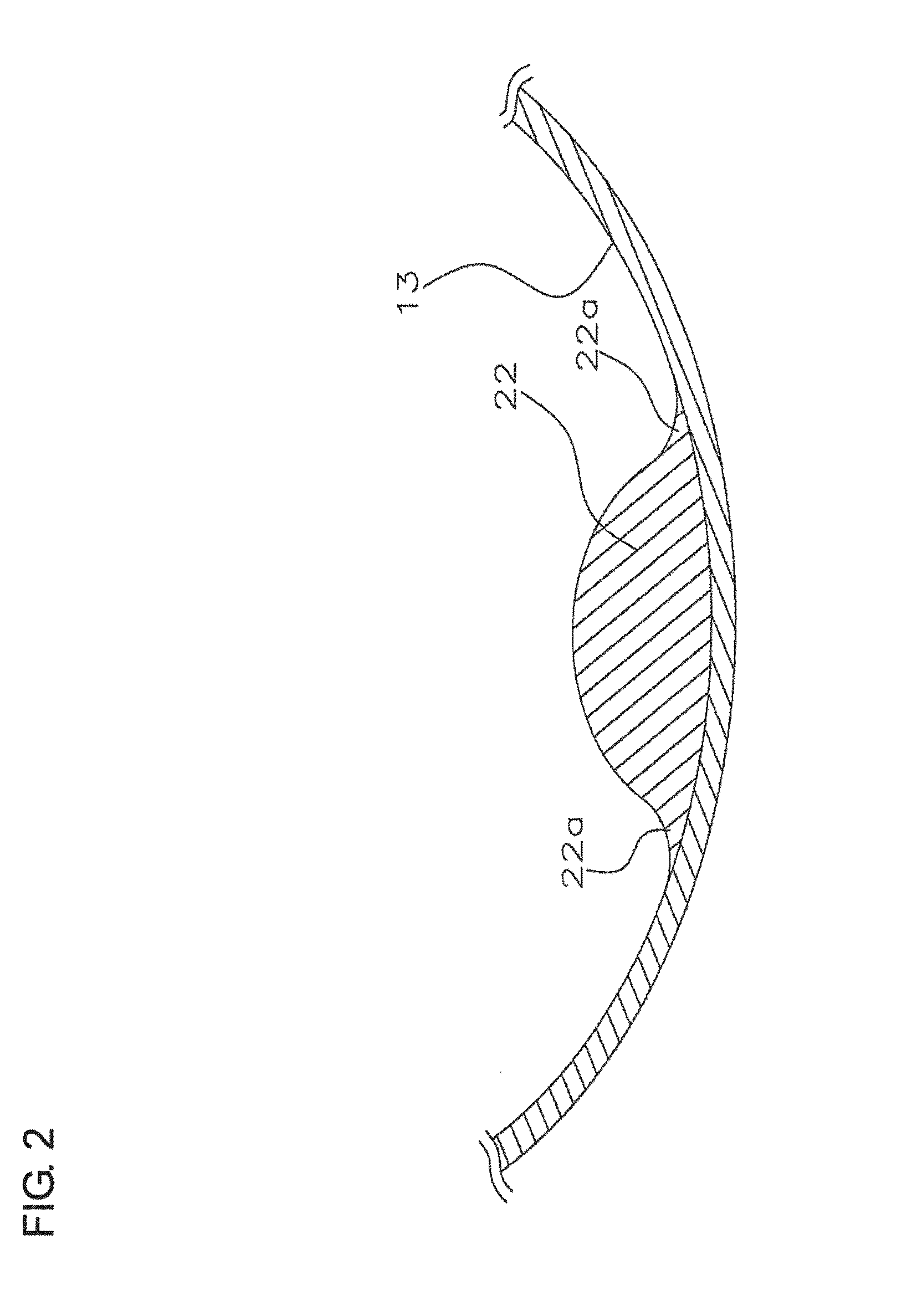
[0036]A first embodiment will be described with reference to FIGS. 1 and 2, and as shown in FIG. 1, a vent (or ventilation) duct 1 according to this first embodiment has duct body portion in which a passage formed in an inner periphery thereof, and the passage is bent to form a bent (curved) portion 11. A protruded portion 20 is formed to a portion of the inner peripheral surface of the vent duct 1 so as to protrude inward at a position downstream side of the bent portion 11.

[0037]Further, the vent duct 1 of the present embodiment is formed of a thermoplastic synthetic resin such as polypropylene group resin material, polyamide group resin material, or the like resin material, and the protruded portion 20 is formed integrally with the vent duct 1 at the time of injection molding process.

[0038]The protruded portion 20 is formed from an upstream side (front side) end portion 21 gently continuous to the inner peripheral surface 12 on the upstream side of the bent portion 11 in the flui...

second embodiment

[0043]Fig. is an illustrated plan view showing an outer shape of a protruded portion formed to the vent duct according to a second embodiment of the present invention. It is further to be noted that the same reference numerals are denoted to portions or parts corresponding to those of the first embodiment shown in FIGS. 1 to 3, and detailed explanations will be omitted herein.

[0044]With reference to FIG. 4, a protruded portion 25 of the vent duct of the present embodiment has the upstream side end portion 21 of the body 22 having the shape extending toward the downstream side of the passage, which is similar to that of the protruded portion 20 of the first embodiment shown in FIG. 3, but the shape of the downstream side end portion 23 differs from that of the protruded portion 20 of the first embodiment.

[0045]The protruded portion 25 of the vent duct of the present embodiment has a downstream side end portion of the body portion having a width gradually reduced toward the perpendicu...

third embodiment

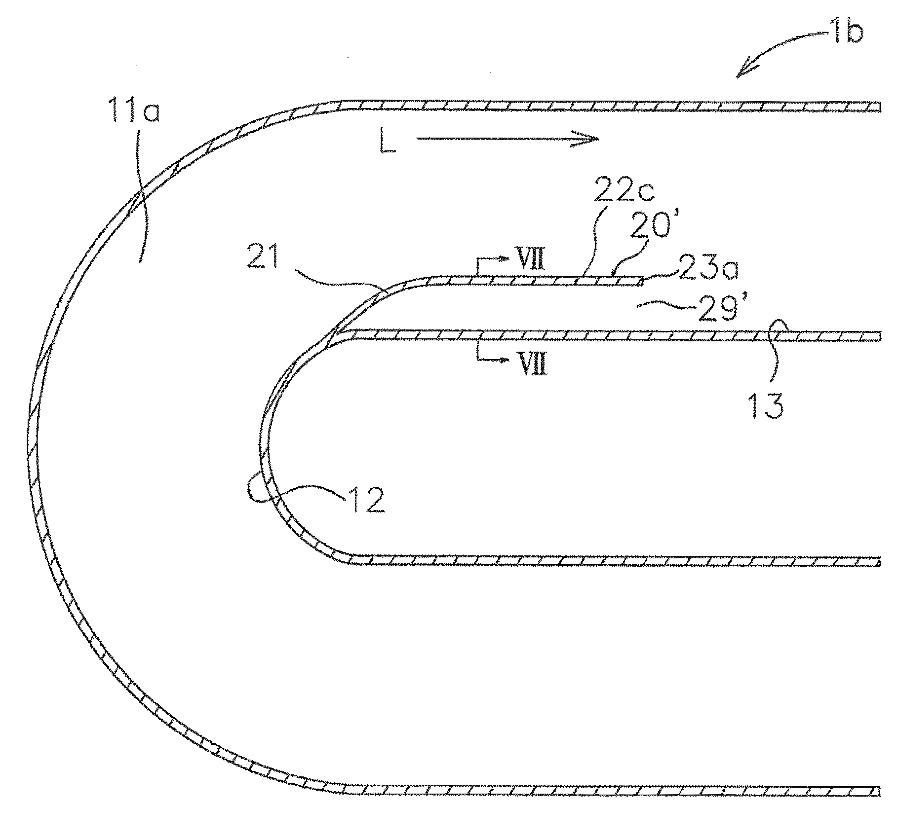
[0048]FIG. 5 is a sectional view, similar to that of FIG. 1, showing a structure of a vent duct according to the third embodiment of the present invention. It is further to be noted that the same reference numerals are denoted to portions or parts corresponding to those of the first or second embodiment shown in FIGS. 1 to 4, and detailed explanations will be omitted herein.

[0049]As shown in FIG. 5, a protruded portion 28 of a vent duct 1a according to the present third embodiment has a structure such that a downstream side duct wall is raised toward the axial center of the passage in the vent duct 1a so as to provide a hollow structure having an opening opened outward of the vent duct 1a. Furthermore, a through hole as an adjustment hole 29 is formed in a perpendicular surface portion 23a formed to the downstream side end of the body portion 22b, and the adjustment hole 29 is communicated to an external side of the vent duct 1a through the opening formed in the inner hollow structu...


PUM

PropertyMeasurementUnit
anglesaaaaaaaaaa
anglesaaaaaaaaaa
diameteraaaaaaaaaa

Abstract

A vent duct having an inner fluid flow passage includes a bent portion formed to a duct body portion at which the fluid flow passage is bent, and a protruded portion formed on a downstream side of the bent portion so as to protrude from an inner peripheral surface portion toward an axial center of the fluid flow passage, wherein the protruded portion includes an upstream side end portion formed to be gently continuous to the inner peripheral surface portion of a downstream side portion of the bent portion, a body portion extending from the upstream side end portion toward the downstream side portion along the fluid flow passage, and a downstream side end portion along the fluid flow passage to be continuous to the body, the downstream side end portion of the protruded portion being formed to be perpendicular to the inner peripheral surface portion.

Description

BACKGROUND OF THE INVENTION[0001]1. Field of the Invention[0002]The present invention relates to a vent (ventilation) duct particularly having a cylindrical structure mounted for introducing an outdoor air into an internal combustion engine.[0003]2. Related Art[0004]In a conventional technology, a cylindrical vent (ventilation) duct for introducing outdoor air into an internal combustion engine has been provided, and for such a vent duct, various means and attempts have been performed for the purpose of reducing ventilation air-flow resistance in order for appropriately introducing and guiding the outdoor air flow.[0005]One of such means is provided by Japanese Patent Laid-open Publication No. 2002-156977 (Patent Document 1) as silencing device in which a guide block having a semi-circular cross-section and attaining acoustic function is provided on an inner peripheral surface at an inner downstream side of a bent (curved) portion of a duct.[0006]The silencing device disclosed in th...

Claims


Application Information

Patent Timeline
Patent Type & Authority Applications(United States)
IPC IPC(8): F16L9/00
CPCF15D1/04F16L9/00F02M35/10262F02M35/1211F02M35/10124F24F13/081F24F13/22F24F13/02F16L43/008F16L43/00Y02T10/146Y02T10/12
Inventor SHIGA, TAKEKIAMANO, TAKAHIROHIRAI, MASAHARU
Owner ROKI CO LTD
Why Eureka
Try Eureka