LED (light emitting diode) fluorescent lamp

A technology of LED fluorescent lamps and LED lamp groups, which is applied in the electronic field, can solve the problems of poor heat dissipation and unfavorable secondary light distribution of light sources, etc., achieve good secondary light distribution effects, increase effective light mixing, and achieve easy effects

Inactive Publication Date: 2011-07-13
刘昌贵
View PDF0 Cites 40 Cited by
  • Summary
  • Abstract
  • Description
  • Claims
  • Application Information

AI Technical Summary

Problems solved by technology

but from figure 1 It can be seen that the PCB board installed with the LED light source is horizontally installed in the lamp tube, and the PCB is in horizontal contact with the aluminum plate, and its heat dissipation surface is only the contact plane of the two, and its heat dissipation effect is not good.
In addition, the PCB board is placed horizontally in the LED lamp tube, which is not conducive to the secondary light distribution of the light source.

Method used


Image

  • LED (light emitting diode) fluorescent lamp
  • LED (light emitting diode) fluorescent lamp
  • LED (light emitting diode) fluorescent lamp

Examples


Embodiment Construction

[0026] The following will clearly and completely describe the technical solutions in the embodiments of the present invention with reference to the drawings in the embodiments of the present invention.

[0027] The LED fluorescent lamp of the present invention comprises a fluorescent lamp tube, a fluorescent lamp end cover installed at both ends of the fluorescent lamp tube, and a metal needle connected between the LED lamp group in the fluorescent lamp tube and the end cover for The constant current source circuit for power supply of the LED lamp group.

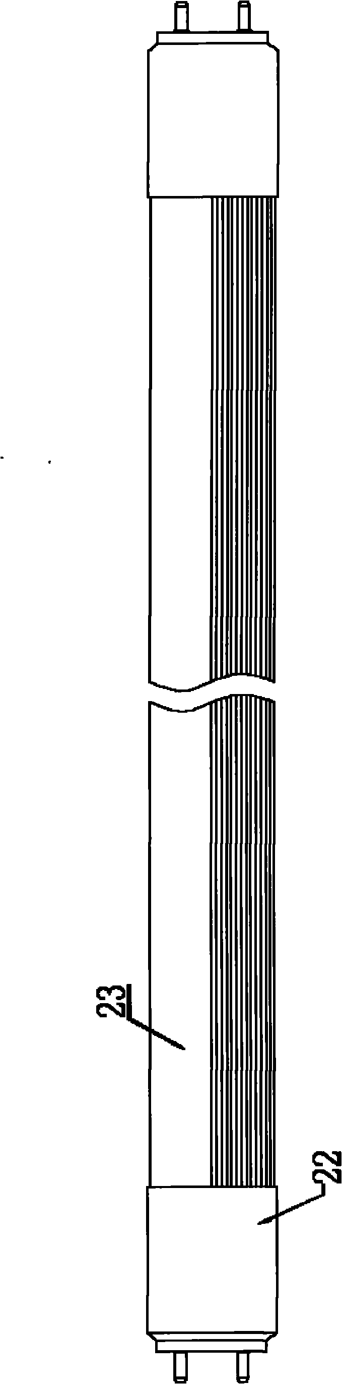
[0028] The external structure of fluorescent lamp of the present invention is as figure 2 As shown, the fluorescent lamp end caps 22 are respectively installed at both ends of the fluorescent lamp tubes 23 on the two fluorescent lamp end caps. Since the constant current source circuit is inside the end caps or the lamp tubes, it is not shown in this figure.

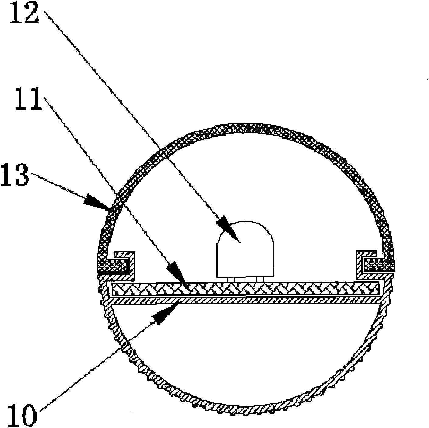
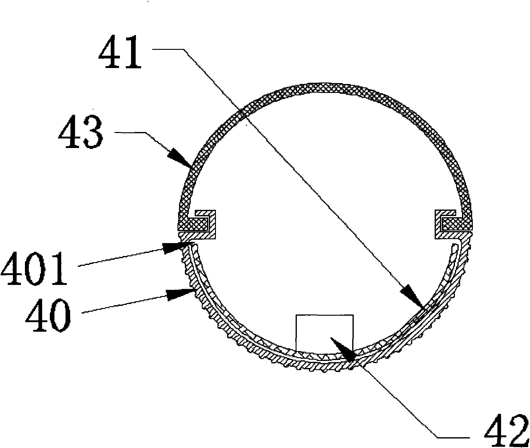
[0029] The cross-sectional structure of an embodiment of the flu...


PUM


Abstract

The embodiment of the invention discloses an LED (light emitting diode) fluorescent lamp which comprises a fluorescent lamp tube, fluorescent lamp end covers and a constant current source circuit, wherein the fluorescent lamp end covers are installed at two ends of the fluorescent lamp tube; the constant current source circuit is connected between an LED lamp bank in the fluorescent lamp tube and the metal needles of the end covers, and is used for supplying electricity for the LED lamp bank. The LED fluorescent lamp is characterized in that the fluorescent lamp tube comprises a tube body; the tube body is composed of an arc-shaped metal sectional material and a transmitting lamp cover which is arranged above the metal sectional material; the part, which is positioned at the inner side of the tube body, of the metal sectional material is provided with a clamping groove; a flexible PCB (printed circuit board) which has bending radian same as that of the metal sectional material is buckled on the clamping groove; and the LED lamp bank is welded on the flexible PCB. The LED fluorescent lamp has good radiation performance, and the secondary grading effect of the LED is good.

Description

technical field [0001] The invention relates to the field of electronics, in particular to an LED fluorescent lamp. Background technique [0002] The huge advantages of energy saving and environmental protection of LED light sources make it have excellent application prospects in commercial lighting, and LED fluorescent lamps are the most widely used products in commercial lighting. As we all know, LED light sources generate a lot of heat while emitting light, so how to dissipate heat from the light source has always been a hot topic in the industry. figure 1 It shows a cross-sectional view of a commonly used LED fluorescent tube in the market. It can be seen from the figure that the LED fluorescent tube usually includes a lower arc-shaped aluminum plate 10 and a printed circuit buckled on the arc-shaped aluminum plate 10. Board (PCB, Printed Circuit Board) board 11, the LED light source 12 welded on the PCB board and the light-transmitting lampshade 13 covered on the arc-s...

Claims


Application Information

Patent Timeline
Patent Type & Authority Applications(China)
IPC IPC(8): F21S2/00F21V15/02F21V23/00F21V29/00F21V23/06H05B37/02H05K1/03F21Y101/02
CPCH05B33/0812F21K9/17F21Y2103/003F21V29/004Y02B20/345F21Y2101/02F21V23/06F21V29/507F21V29/77F21K9/272F21K9/275F21Y2103/10F21Y2115/10H05B45/395Y02B20/30
Inventor 刘昌贵
Owner 刘昌贵
Why Eureka
Try Eureka