Permanent magnet speed regulator with fixed magnetic gap

A technology of permanent magnet governor and fixed magnet, which is applied in the direction of permanent magnet clutches/brakes, etc., which can solve the problems of inability to rotate and drive loads, and achieve the effects of saving installation space, reducing overall volume, and saving rare earth materials

Active Publication Date: 2016-03-30
刁俊起
View PDF6 Cites 1 Cited by
  • Summary
  • Abstract
  • Description
  • Claims
  • Application Information

AI Technical Summary

Problems solved by technology

In order to solve the above problems, the patent CN201520071349 proposes a permanent magnet governor with a fixed magnetic gap, but when the first inner magnetic rotor and the second inner magnetic rotor rotate, the corresponding relationship between the first permanent magnet and the second permanent magnet The polarity of the magnetic pole is constantly switched between the same and different, which causes the driven shaft to oscillate continuously in two directions, and cannot normally rotate in one direction to drive the load

Method used


Image

  • Permanent magnet speed regulator with fixed magnetic gap
  • Permanent magnet speed regulator with fixed magnetic gap
  • Permanent magnet speed regulator with fixed magnetic gap

Examples


Embodiment 1

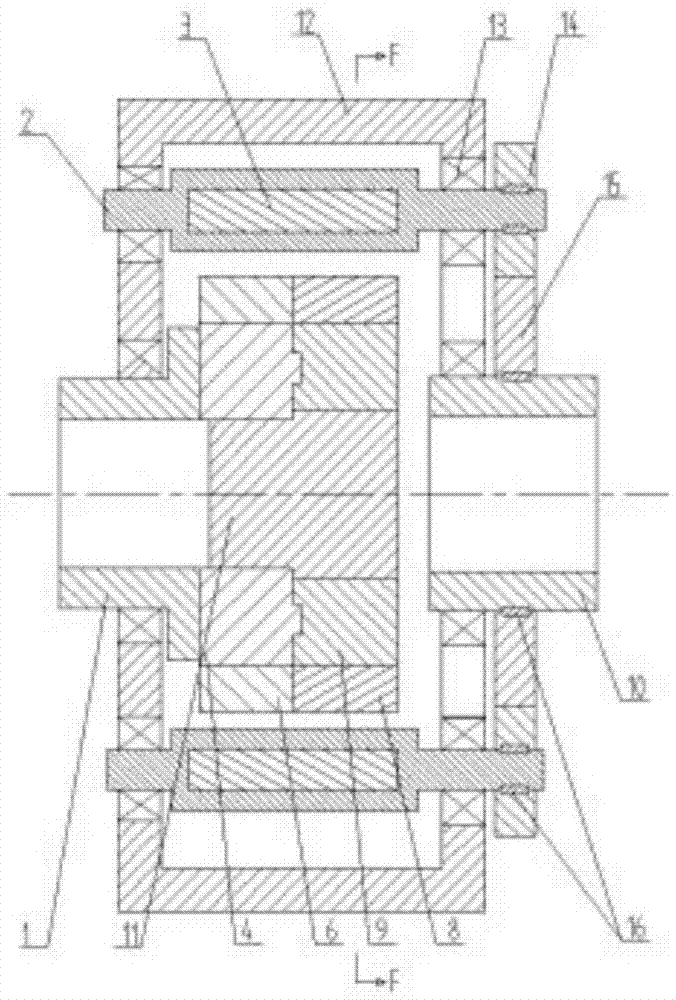
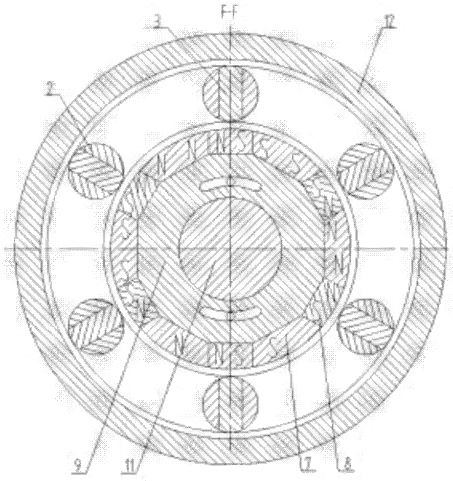
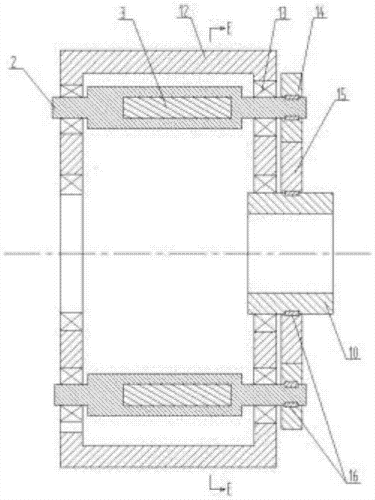
[0026] A permanent magnet governor with a fixed magnetic gap, including a first inner magnetic rotor 4 and a second inner magnetic rotor 9 through which a driving shaft 1 passes concentrically, an outer magnetic rotor frame 12 connected to a driven shaft 10, and an outer magnetic rotor 2. The outer magnetic rotor 2 is mounted on the outer magnetic rotor frame 12 through bearings 13 assembled at both ends, and the bearings 13 can be one-way bearings or two-way bearings. In addition, an outer magnetic rotor planetary gear 14 is connected to the end of the outer magnetic rotor close to the driven shaft through a key 16 or a one-way bearing, and a driven shaft planetary gear 15 is installed between the outer magnetic rotor planetary gear 14 and the driven shaft 10; The outer magnetic rotor 2 is uniformly distributed with at least two outer permanent magnets 3 along its inner circumferential surface, and the first inner magnetic rotor 4 and the second inner magnetic rotor 9 are unif...

Embodiment 2

[0028] A permanent magnet governor with a fixed magnetic gap, each inner permanent magnet magnetic pole is arranged radially, the magnetic poles on the adjacent sides of two adjacent inner permanent magnets on the same inner magnetic rotor are different, and the rest is the same as the first embodiment.


PUM


Abstract

The invention relates to a permanent magnet speed regulator with a fixed magnetic gap, and the speed regulator comprises a first internal magnetic rotor, a second internal magnetic rotor, and an external magnet rotor frame, wherein a driving shaft coaxially passes through the first and second internal magnetic rotors, and the external magnet rotor frame is connected with a driven shaft. The external magnet rotor frame is provided with an external magnetic rotor through a bearing. In addition, one end, close to the driven shaft, of the external magnetic rotor is provided with an external magnetic rotor planetary gear. A driven shaft planetary gear is disposed between the external magnetic rotor planetary gear and the driven shaft. The speed regulator employs a fixed magnetic gap structure, so the speed regulator greatly increases the engagement area, reduces the assembly difficulty, reduces the generated heat, enlarges the range of speed regulation, saves rare earth materials, and greatly improves the capability of torque transmission. Because the speed regulator employs a planetary gear transmission structure, the speed regulator achieves a function of 0-%N speed regulation of input and output rotating speeds through changing the gear ratio of the external magnetic rotor planetary gear to the driven shaft planetary gear. In addition, the speed regulator employs a bearing structure, and prevents the continuous shaking of the driven shaft in two directions from causing that the driven shaft cannot rotate normally in one direction to drive a load.

Description

technical field [0001] The invention relates to a permanent magnet governor, in particular to a permanent magnet governor with a fixed magnetic gap. Background technique [0002] The permanent magnet speed governor uses the magnetic coupling speed of the permanent magnet to realize the soft (magnetic) connection between the motor and the load, without any harmonic generation affecting the power grid, and has high reliability. , Inflammable and explosive, voltage instability and lightning and other harsh environments, greatly reducing mechanical vibration, widely used in electric power, steel, metallurgy, petrochemical, papermaking, municipal, ships, irrigation and mining industries. At present, the commonly used permanent magnet governors realize the speed adjustment by adjusting the air gap. The magnetic circuit regulator consumes a lot of power, and has disadvantages such as poor torque transmission capability, high assembly difficulty, and waste of a large amount of rare ...

Claims


Application Information

Patent Timeline
Patent Type & Authority Applications(China)
IPC IPC(8): H02K49/10
Inventor 刁俊起李强张磊王忠亮王秀张学凯
Owner 刁俊起
Why Eureka
Try Eureka