
Worm gear structure

A worm gear and semi-worm gear technology, which is applied to belts/chains/gears, portable lifting devices, components with teeth, etc., can solve the problems of low processing efficiency, high cost and poor processing consistency of worm gears, and achieve good self-locking effect. , increased yield, easy consistency effect

Inactive Publication Date: 2016-12-21
ZHEJIANG JIECHANG LINEAR MOTION TECH
View PDF6 Cites 1 Cited by
  • Summary
  • Abstract
  • Description
  • Claims
  • Application Information

AI Technical Summary

Problems solved by technology

[0003] The purpose of the present invention is to provide a worm gear structure to solve the existing technical problems of low processing efficiency, high cost and poor processing consistency of worm gears

Method used


Image

  • Worm gear structure
  • Worm gear structure

Examples


Embodiment Construction

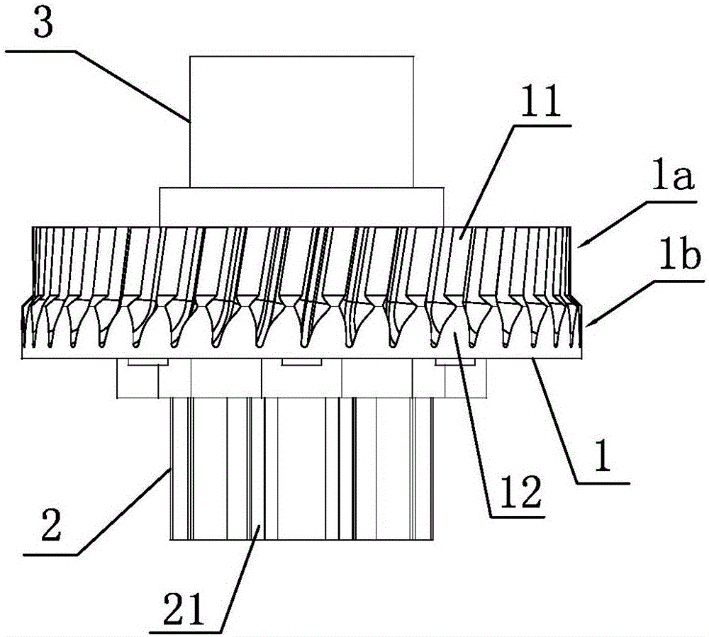
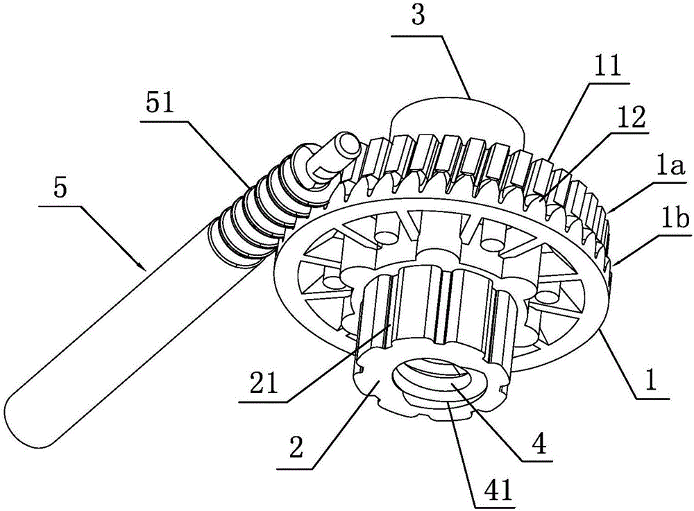
[0017] Such as figure 1 with figure 2 As shown, the present invention provides a worm gear structure, including a wheel body 1, the outer peripheral surface of the wheel body 1 includes a first outer peripheral surface 1a and a second outer peripheral surface 1b, and helical gear teeth 11 are evenly distributed on the first outer peripheral surface 1a, Half worm gear teeth 12 in the shape of half worm gear teeth are evenly distributed on the second outer peripheral surface 1b. The tooth portion of the structure is cut radially to form roughly half a worm gear tooth structure, wherein the helical gear tooth portion 11 and the half worm gear tooth portion 12 are in one-to-one correspondence and connected in the radial direction. Therefore, the helical gear tooth portion The tooth grooves formed by 11 and the tooth grooves formed by the half worm gear part 12 are correspondingly connected one by one, and the wheel body 1, the helical gear tooth part 11 and the half worm gear pa...


PUM


Abstract

The invention discloses a worm gear structure, belongs to the technical field of transmission devices, and solves the technical problem that a conventional worm gear is low in processing efficiency, high in cost and poor in processing uniformity. The technical scheme which solves the problem lies in that the worm gear structure mainly comprises a gear body; peripheral surfaces of the gear body comprise a first peripheral surface and a second peripheral surface; bevel gear tooth parts are uniformly distributed on the first peripheral surface; half-worm gear tooth-shaped half-worm gear tooth parts are uniformly distributed on the second peripheral surface; the bevel gear tooth parts and the half-worm gear tooth parts are in one-to-one correspondence and are connected in the radial direction; and the gear body, the bevel gear tooth parts and the half-worm gear tooth parts are formed through integral casting.

Description

technical field [0001] The invention belongs to the technical field of transmission devices and relates to a worm gear structure. Background technique [0002] The worm gear transmission structure is widely used in the field of mechanical transmission. The teeth on the existing worm gear are made by hobbing or cutting, followed by finishing processes such as shaving, honing or grinding. There are low processing efficiency and The disadvantage of high cost, and also due to differences in hobs, clamping and other factors lead to poor processing consistency. Contents of the invention [0003] The purpose of the present invention is to provide a worm gear structure to solve the technical problems of low processing efficiency, high cost and poor processing consistency of the existing worm gear. [0004] In order to achieve the above object, the present invention adopts the following technical solution: a worm wheel structure, including a wheel body, the outer peripheral surfac...

Claims


Application Information

Patent Timeline
Patent Type & Authority Applications(China)
IPC IPC(8): F16H55/22
CPCF16H55/22
Inventor 陆小健胡仁昌潘柏鑫程云山石鑫
Owner ZHEJIANG JIECHANG LINEAR MOTION TECH
Learn More