

Pneumatic Tire
a pneumatic tire and tire body technology, applied in the field of pneumatic tires, can solve the problems of pneumatic tires disclosed in documents, irregular wear, and increased rolling resistance, and achieve the effects of reducing deformation of blocks and hysteresis loss, increasing rolling resistance, and reducing rolling resistan
Active Publication Date: 2009-10-29
TOYO TIRE & RUBBER CO LTD
View PDF3 Cites 24 Cited by
- Summary
- Abstract
- Description
- Claims
- Application Information
AI Technical Summary
Benefits of technology
[0008]The present invention has been made under these circumstances. The object of the present present invention is to provide a pneumatic tire having low rolling resistance and higher resistance against irregular wear.
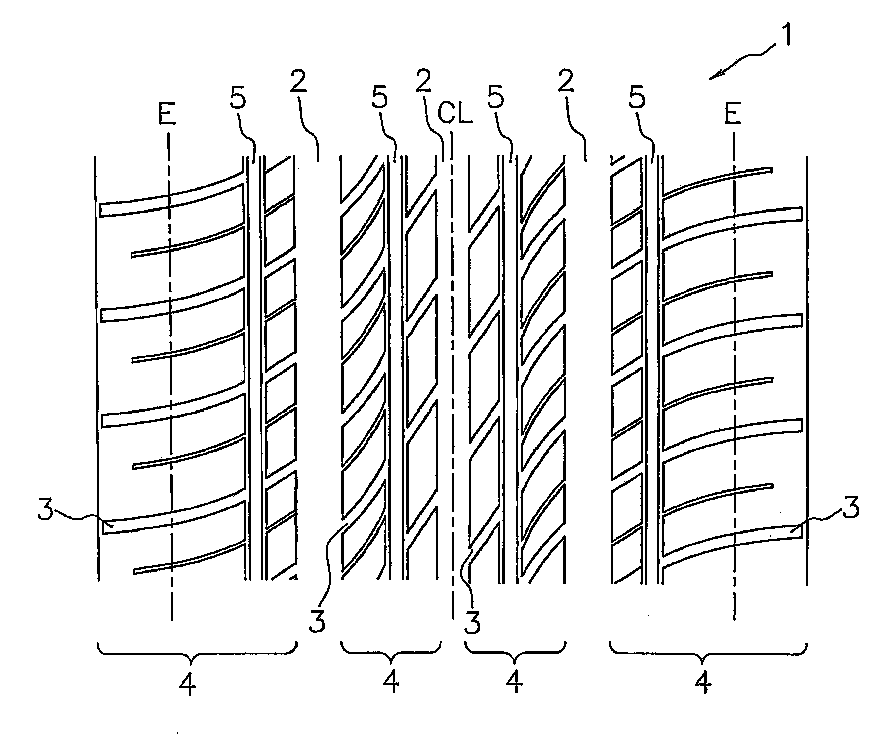
[0010]The pneumatic tire according to the present invention is arranged in such a way that, in at least one block array, a thin rib continuously extending in the circumferential direction of the tire is formed, so that the rigidity of the block array can be increased. As a result, deformation of the block and the hysteresis loss are reduced; and accordingly the rolling resistance can be reduced. Further, the thin rib continuously extending in the circumferential direction of the tire is disposed in a central area of the block array as viewed in the width direction of the tire. Therefore, when the tire comes into contact with the ground, slip of blocks can be uniformly reduced in the entire block array, and thus the rigidity difference among the blocks can be reduced. As a result, irregular wear can be prevented in the block array.
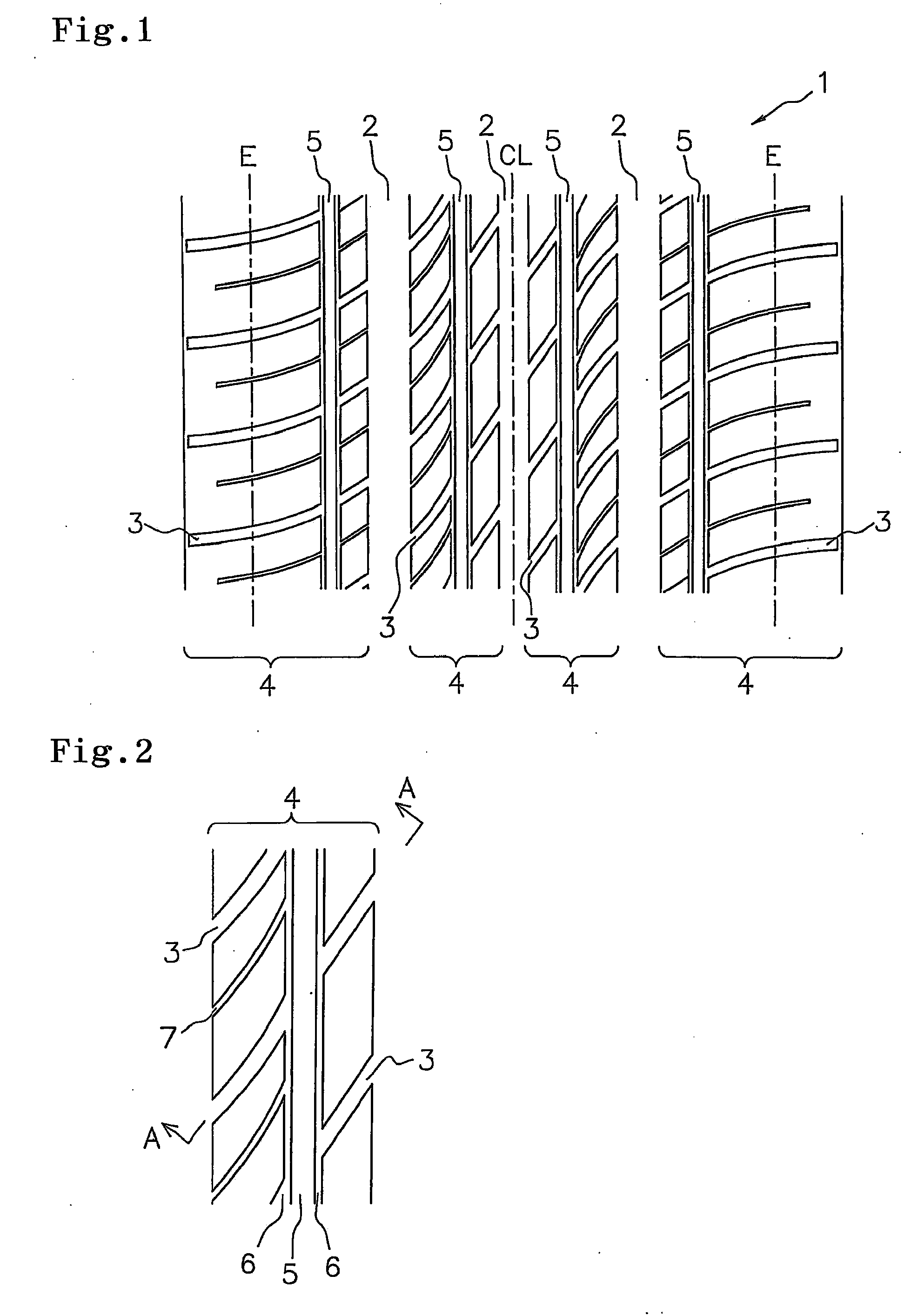
[0011]The thin rib continuously extending in the circumferential direction of the tire is partitioned by the two sipes extending in the circumferential direction of the tire. The rigidity difference is reduced between the thin rib and the blocks that abut on the thin rib being interposed by the sipes extending in the circumferential direction of the tire. As a result, the difference in rigidity is eliminated between the thin rib and the blocks in the block array. Accordingly, the entire block array can be prevented from being worn irregularly. Furthermore, since the sipes extending in the circumferential direction of the tire partition the thin rib, the rigidity of the thin rib is reduced so that the riding quality of the tire can be increased.
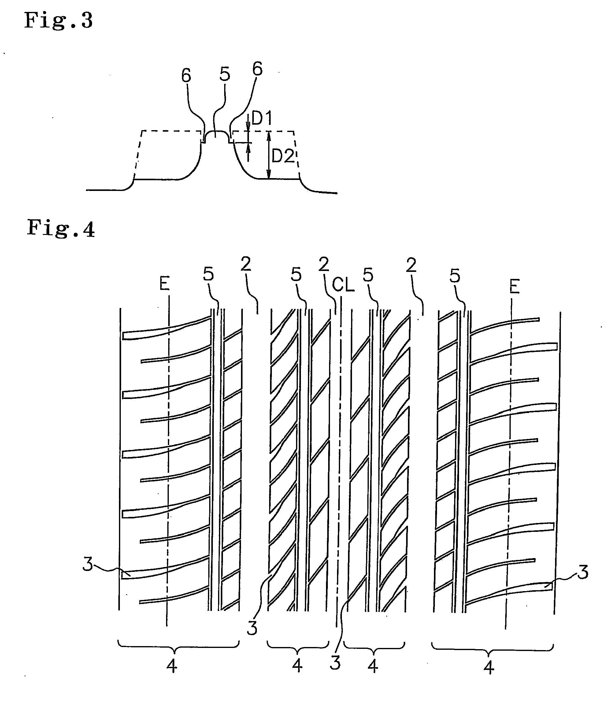
[0012]In the above tire, the edges of the thin rib are preferably chamfered. With this arrangement, the rigidity difference between the thin rib and the blocks that abut on the thin rib being interposed by the sipes extending in the circumferential direction of the tire is reduced. As a result, difference in rigidity is eliminated between the thin rib and the blocks in the block array. Thus, the entire block array can be effectively prevented from being worn irregularly.
Problems solved by technology
However, in such pneumatic tires, a large deformation is generated on the blocks during running, and as the hysteresis loss increases, rolling resistance tends to increase.
Also, rigidity difference among the blocks tends to cause irregular wear such as stepped wear.
However, such pneumatic tires disclosed in the documents have problems as described below.
Irregular wear tends to be generated in such block array.
As a result, deformation amount of the block becomes larger, and as the hysteresis loss increases, the rolling resistance tends to increase in the block array.
Therefore, a rigidity difference tends to be generated between the respective blocks in a circumferential direction of the tire causing irregular wear in the block array.
Therefore, the pneumatic tire is not intended to solve the problem; i.e., to reduce the deformation amount of the block and to reduce the rigidity difference among the blocks.
Method used
View moreImage
Smart ImageViewing Examples

Examples
example 1
[0035]The following pneumatic tire was prepared. That is, in the tread portion 1 as shown in FIG. 1, the width of the thin rib 5: 4 mm; curvature radius of chamfered edges of the thin rib 5: 1.5 mm; location of thin rib 5: center line of block array 4 was located in a 50% area of width of the block array 4 with respect to the end at tire equator line CL side as viewed in a width direction of the tire; the depth of the sipes 6 extending in the circumferential direction of the tire: 2 mm; the width the sipes: 1 mm; depth of the lateral groove 3: 7 mm; and width of the lateral groove 3: 3 mm. Using this tire, the above-described performance tests were carried out. The results are shown in Table 1.
Login to View More PUM
 Abstract
An object of the present invention is to provide a pneumatic tire having low rolling resistance and higher resistance against irregular wear. To achieve the above object, a pneumatic tire includes a tread portion comprising a plurality of block arrays each of which is constituted of a plurality of blocks that are partitioned by a plurality of main grooves extending in a circumferential direction of the tire and a plurality of lateral grooves crossing the main grooves, wherein at least one of the block arrays is provided with a thin rib that continuously extends in the circumferential direction of the tire in a central area of the block array as viewed in a width direction of the tire and is partitioned by two sipes extending in the circumferential direction of the tire, the depth of the sipes extending in the circumferential direction of the tire is 0.7 times or less of the depth of the lateral grooves.
Description
BACKGROUND OF THE INVENTION[0001]1. Field of the Invention[0002]The present invention relates to a pneumatic tire, including a tread portion comprising a plurality of block arrays each of which is constituted of a plurality of blocks that are partitioned by a plurality of main grooves extending in a circumferential direction of the tire and a plurality of lateral grooves crossing the main grooves. The pneumatic tire has low rolling resistance and higher resistance against irregular wear.[0003]2. Description of the Related Art[0004]Generally, pneumatic tires have a tread portion formed with a plurality of block arrays, and traction performance is satisfactorily ensured. Such pneumatic tires are excellent in braking, turning and cornering characteristics. However, in such pneumatic tires, a large deformation is generated on the blocks during running, and as the hysteresis loss increases, rolling resistance tends to increase. Also, rigidity difference among the blocks tends to cause ir...
Claims
Login to View More Application Information
Patent Timeline
 IPC IPC(8): B60C11/117B60C11/12
CPCB60C11/0306B60C2011/1231B60C11/1392B60C11/0309Y02T10/86
InventorSATO, YOSHIKI
OwnerTOYO TIRE & RUBBER CO LTD