Commutation torque ripple restraining method and system for brushless DC (Direct Current) motor driving system

A brushed DC motor and drive system technology, applied in the field of mechanical engineering, can solve the problems of sensitive motor parameters, lack of universal applicability, and difficulty in determining the commutation time.

Inactive Publication Date: 2014-01-08
CENTRAL SOUTH UNIVERSITY OF FORESTRY AND TECHNOLOGY
View PDF4 Cites 24 Cited by
  • Summary
  • Abstract
  • Description
  • Claims
  • Application Information

AI Technical Summary

Problems solved by technology

[0003] In the prior art, some control the terminal voltage of each winding during commutation to make the current rising speed of the off phase and the access phase equal, but the chopping time is not easy to grasp; some propose an improved bipolar The permanent PWM brushless DC motor control method uses four switching tubes to perform PWM control at the same time, but this method increases the frequency of switching tubes; some documents use current sensors and torque observers to determine the three-phase PWM modulation range, but this method is extremely sensitive to motor parameters and lacks universal applicability; some literature proposes a method for calculating the current commutation interval through motor parameters, but this method needs to calculate the inductance value of the motor stator winding; some literature proposes a hysteresis loop current control method, but no specific solution is given for torque ripple suppression in high-speed areas; some literature proposes a three-phase PWM modulation strategy within the full speed range to suppress torque ripple during commutation, which simplifies the control process, but Ignoring the essential characteristics of torque ripple in the high and low speed range, the control effect is not good in the extreme speed range; some literatures have introduced a novel three-stage PWM commutation torque ripple suppression strategy, by switching off phase, The PWM modulation strategy with different duty ratios connected to the phase can achieve the effect of suppressing torque ripple
However, the introduction of two parameters that need to be adjusted makes the system complex and difficult to control; many documents in the prior art have proposed good control methods for suppressing the commutation torque, but the control methods are relatively complicated, commutation torque Difficult to determine the phase time and other issues

Method used


Image

  • Commutation torque ripple restraining method and system for brushless DC (Direct Current) motor driving system
  • Commutation torque ripple restraining method and system for brushless DC (Direct Current) motor driving system
  • Commutation torque ripple restraining method and system for brushless DC (Direct Current) motor driving system

Examples


Embodiment 1

[0073] 1 Mechanism Analysis of Commutation Torque Ripple

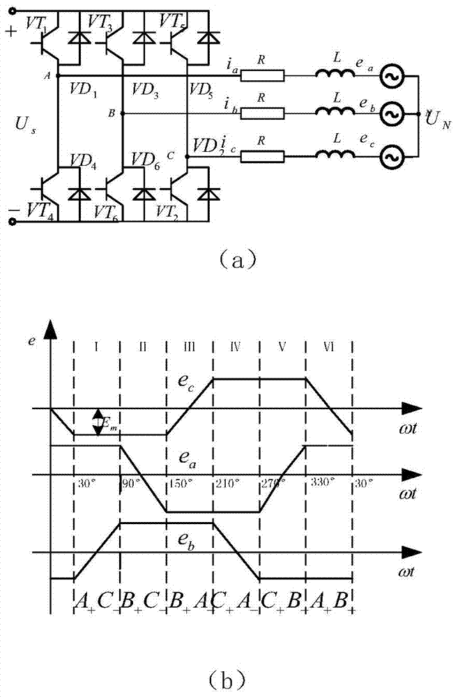
[0074] Two-two conduction three-phase six-state brushless DC motor during commutation, because the stator winding is an inductive element, its current cannot change abruptly. After commutation starts, the off-phase current will not drop to zero immediately, and the on-phase current will not rise to a stable value immediately, that is, the current waveform will not be a standard rectangular wave but a trapezoidal shape during commutation. Only through a special control method or only when certain conditions are met can the drop rate of the off-phase current be equal to the rise rate of the access phase current, otherwise, it will inevitably cause the pulsation of the non-commutation current in the winding, resulting in a commutation switch. torque ripple.

[0075] 1.1 Equivalent circuit analysis of commutation process

[0076] figure 1 It is the equivalent circuit diagram of the brushless DC motor and the ideal thre...


PUM


Abstract

The invention discloses a commutation torque ripple restraining method and a commutation torque ripple restraining system for a brushless DC (Direct Current) motor driving system. The method comprises the following steps: (1) when T*-T is more than AT, carrying out PWM (Pulse Width Modulation) on a switching tube of an off phase, enabling a switching-in phase to be constantly communicated with a non-conducting phase, enabling the PWM duty cycle dhigh of the off switch to meet the condition and ensuring that a current rise speed of the switching-in phase is equal to a current fall speed of the off phase so as to restrain generation of a commutation torque ripple; and (2) when T-T* is more than delta T, carrying out PWM on switching tubes of the switching-in phase and the non-conducting phase, still switching off the off phase and enabling the PWM duty cycle dlow of the switching tubes of the switching-in phase and the non-conducting phase of the off phase to meet the condition. The method uses a torque ripple deviation as a feedback quantity and is matched with PWM to implement torque ripple restraint, has an excellent effect and is easy to implement.

Description

technical field [0001] The invention belongs to the field of mechanical engineering, and relates to a commutation torque ripple suppression method and system for a brushless DC motor drive system. Background technique [0002] When analyzing the permanent magnet brushless DC motor, it is always assumed that its back EMF waveform is a trapezoidal wave with a flat top width of 120°. However, during the manufacturing process of the motor, technological problems such as insufficient rotor magnetization and asymmetrical windings may occur, and it is difficult to achieve an ideal trapezoidal wave in the actual back EMF waveform of the permanent magnet brushless DC motor. Therefore, the traditional current and speed double closed-loop control will produce larger torque ripple and poor dynamic performance. In addition, many factors such as cogging design process, current commutation, and armature reaction will also cause torque ripple of brushless DC motors, among which current com...

Claims


Application Information

Patent Timeline
Patent Type & Authority Applications(China)
IPC IPC(8): H02P21/05
Inventor 朱俊杰
Owner CENTRAL SOUTH UNIVERSITY OF FORESTRY AND TECHNOLOGY
Why Eureka
Try Eureka