This helps you quickly interpret patents by identifying the three key elements:
Problems solved by technology
Method used
Benefits of technology
Benefits of technology
[0010]the drive of the plurality of switching elements by the control system disclosed in the Japanese Patent Application Publication during a low RPM of the multiphase rotary machine reduces the percentage of the durations in which the power converter is driven in the zero vector mode as compared with the drive of the plurality of switching elements in a well-known triangular PWM control mode.
[0015]For this reason, periods during which a value of the current actually flowing through each phase winding of the rotary machine is deviated higher or lower from the command current value may be extended. This may result in reducing the control accuracy of torque to be created by the multiphase rotary machine.
[0016]In view of the background, an object of at least one aspect of the present invention is to provide control systems for a multiphase rotary machine. These control systems are capable of driving a switching element of a power converter so as to control the difference between a value of a current actually flowing in the multiphase rotary machine and a command current value within an allowable range while more properly increasing durations in which the power converter is driven in the zero vector mode.
Problems solved by technology
This may increase surges due to each switching.
Method used
Image
Click on the blue label to locate the original text in one second.
Reading with bidirectional positioning of images and text.
Examples
first embodiment
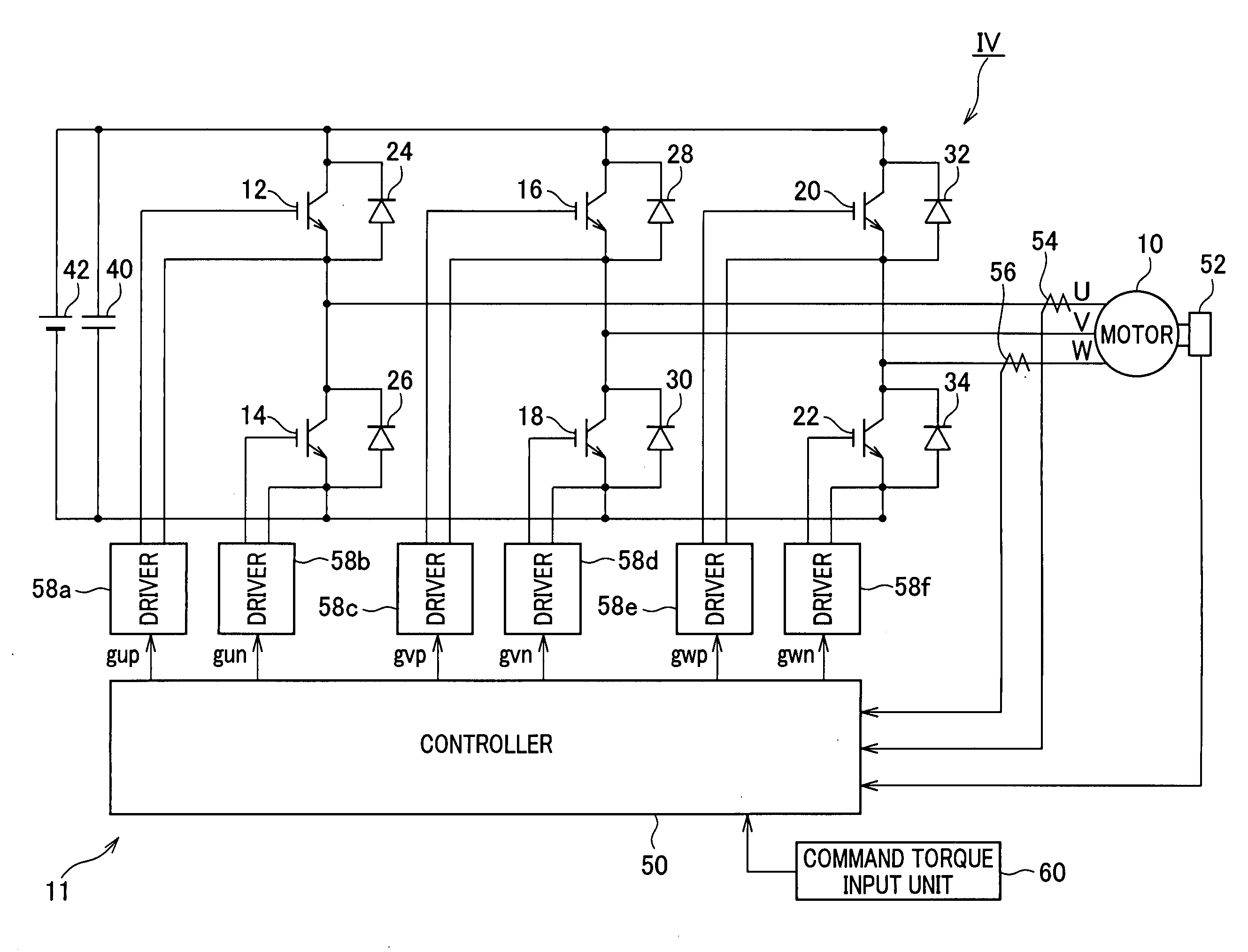
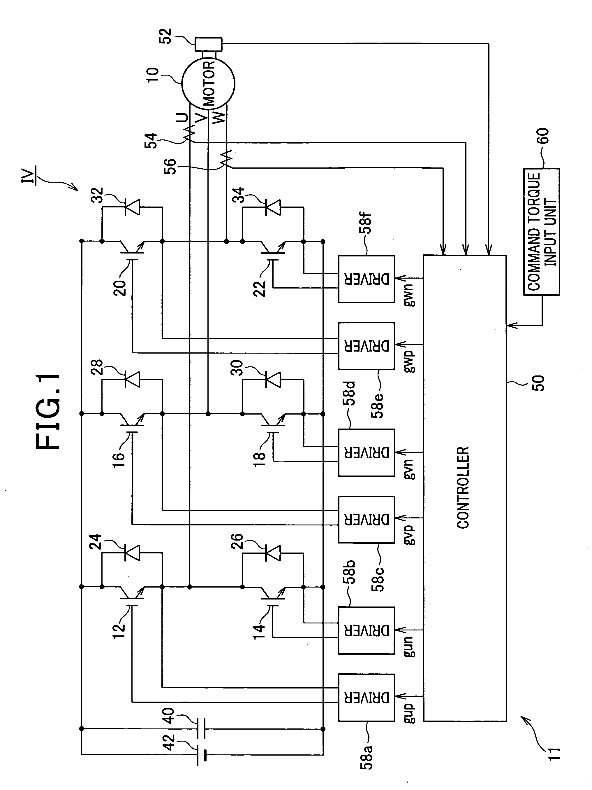
[0045]Referring to the drawings, particularly to FIG. 1, there is illustrated a three-phase brushless motor, referred to simply as “motor”, 10 and a control system 11 for controlling the motor 10.
[0046]For example, the motor 10 is provided with an annular rotor having a rotor core. The rotor core of the rotor is provided at its circumferential portion with at least one N and S pole pair. The rotor has a direct axis (d-axis) in line with a rotor N pole center line, and has a quadrature axis (q-axis) whose phase is π / 2 radian electric angle leading with respect to a corresponding d-axis during rotation of the rotor.
[0047]The stator includes a stator core with, for example, an annular shape in its lateral cross section. The stator core is for example disposed around the outer periphery of the rotor core such that the inner periphery of the stator core is opposite to the outer periphery of the rotor core with a predetermined air gap.
[0048]The stator core also has a plurality of slots. T...
second embodiment
[0374]A control system according to a second embodiment of the present invention will be described hereinafter with reference to FIG. 24.
[0375]The structure of the control system according to the second embodiment is substantially identical to that of the control system 11 according to the first embodiment. So, like parts between the control systems according to the first and second embodiments, to which like reference characters are assigned, are omitted or simplified in description.
[0376]Referring to FIG. 4, each of the modules 80, 82, and 84 according to the second embodiment includes a common logic function illustrated in FIG. 22.
[0377]Specifically, as can be seen from the comparison between the respective routines illustrated in FIGS. 7, 8, and 11, the logic structures of the respective routines illustrated in FIGS. 7, 8, and 11 are identical to each other. In other words, each of the routines illustrated in FIGS. 7, 8, and 11 has a common logic structure, individual vectors wi...
PUM
Abstract
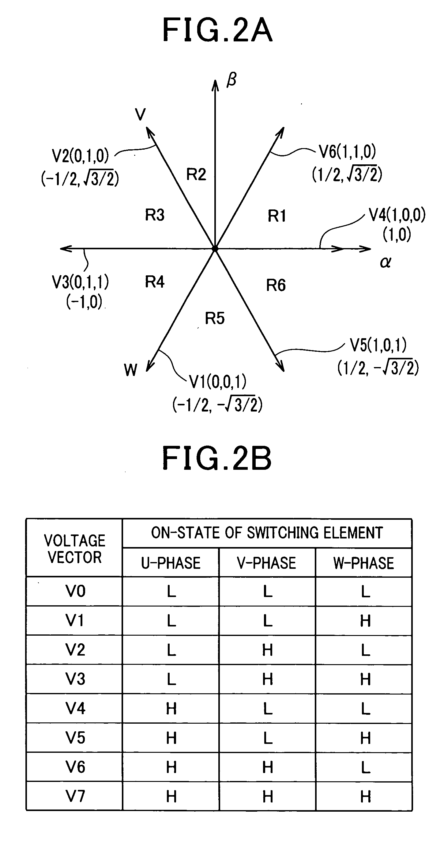
A control system is designed to use a plurality of voltage vectors expressing a switching mode for a switching circuit to thereby control a difference between a current actually flowing through a multiphase rotary machine and a command current value therefor within an allowable range. The plurality of voltage vectors include a zero vector that allows line-to-line voltages in the multiphase rotary machine to be all zero, and a plurality of non-zero vectors that allow at least one of line-to-line voltage in the multiphase rotary machine to be nonzero. A drive unit is configured to switch only one phase of the switching element for each shift of the switching mode to thereby shift, in accordance with a preset switching pattern, the switching mode from a specified one of the plurality of non-zero vectors to the specified one of the plurality of non-zero vectors via the zero vector.
Description
CROSS REFERENCE TO RELATED APPLICATIONS[0001]This application is based on Japanese Patent Application 2007-327022 filed on Dec. 19, 2007. This application claims the benefit of priority from the Japanese Patent Application, so that the descriptions of which are all incorporated herein by reference.FIELD OF THE INVENTION[0002]The present invention relates to control systems for multiphase rotary machines. More particularly, such control systems are designed to drive a plurality of switching elements of a power converter to thereby control the difference between a value of a current actually flowing in a multiphase rotary machine and a command value for the current such that the difference remains within a preset allowable range.BACKGROUND OF THE INVENTION[0003]An example of such control systems for controlling the difference between a value of a current actually flowing in a multiphase rotary machine and a command value for the current such that the difference remains within a preset...
Claims
Application Information
Patent Timeline
Application Date:The date an application was filed.
Publication Date:The date a patent or application was officially published.
First Publication Date:The earliest publication date of a patent with the same application number.
Issue Date:Publication date of the patent grant document.
PCT Entry Date:The Entry date of PCT National Phase.
Estimated Expiry Date:The statutory expiry date of a patent right according to the Patent Law, and it is the longest term of protection that the patent right can achieve without the termination of the patent right due to other reasons(Term extension factor has been taken into account ).
Invalid Date:Actual expiry date is based on effective date or publication date of legal transaction data of invalid patent.

