Generated torque control method for leg body exercise assistive apparatus

a technology of assistive equipment and generated torque, which is applied in the direction of program control, gymnastic exercise, instruments, etc., can solve the problem of the difference between the actual leg motion pattern and the motion pattern assumed by the person, and achieve the effect of preventing the attachment of a sensor and high degree of freedom

Inactive Publication Date: 2007-10-09
HONDA MOTOR CO LTD
View PDF8 Cites 55 Cited by
  • Summary
  • Abstract
  • Description
  • Claims
  • Application Information

AI Technical Summary

Benefits of technology

[0005]In view of the above background, the present invention has been provided. Therefore, it is an object of the present invention to provide a generated torque control method for a leg body exercise assistive apparatus enabling a person to make a leg motion in such a feeling that the person is not wearing the leg body exercise assistive apparatus as much as possible by reducing the weight of the leg body exercise assistive apparatus attached to the person acting on the person.
[0012]Therefore, according to the first and second features of the present invention, it becomes possible to reduce the empty weight of the leg body exercise assistive apparatus, which is attached to the person, acting on the person, whereby the person can make the leg motion in such a feeling that the person is not wearing the leg body exercise assistive apparatus as far as possible.
[0013]Incidentally, in the first feature of the present invention, the torque generation means for applying the support torque to the ankle joint of each leg is not necessarily required. In this case, while the person incurs more percentage of the empty weight of the leg body exercise assistive apparatus in comparison with the second feature of the present invention, it is possible to reduce the percentage of the empty weight of the leg body exercise assistive apparatus incurred by the person to a relatively low level by applying the torque from the torque generation means to the joint regions corresponding to the hip joint and the knee joint of the leg body exercise assistive apparatus as described above. In order to minimize the percentage of the empty weight of the leg body exercise assistive apparatus that the person incurs, however, preferably the torque generation means applies the torque to the joint regions corresponding to the ankle joint, the knee joint, and the hip joint of each leg as described in the second feature of the present invention.
[0016]According to the third feature of the present invention, the estimated person-side joint moment and apparatus-side joint moment may be components around one axis and the torque generated by the torque generation means may also be a torque around one axis. Therefore, the structure of the leg body exercise assistive apparatus can be compact and simple. At the same time, the torque generated by the torque generation means is controlled by estimating the person-side joint moment and the apparatus-side joint moment related to the bending and stretching motion, which is the main human leg motion, thereby achieving an effective reduction of the load on the person applied by the empty weight of the leg body exercise assistive apparatus.
[0024]The motion state (eventually, the inertia force) of each part of the person can be known by using the acceleration of a predetermined region of the person or the leg body exercise assistive apparatus, the displacements of the joints of each leg of the person, and the person-side rigid link model, thereby allowing an estimation of the floor reaction forces acting on the person by his or her own weight and the application point thereof by a dynamic or geometric calculation. Similarly, by using the acceleration of a predetermined region of the person or the leg body exercise assistive apparatus, the displacements of the joints of each leg of the person, and the apparatus-side rigid link model, it is possible to estimate the floor reaction forces acting on the leg body exercise assistive apparatus by its own weight and the application point thereof. As mentioned above, the leg body exercise assistive apparatus can be downsized by reducing the sensors or the like to be attached to the person by using the acceleration or the like in the predetermined region to estimate the floor reaction forces and the application point thereof. Moreover, in this case, the acceleration sensor necessary for grasping the acceleration is only required to be attached to the region corresponding to a rigid element of either the person-side rigid link model or the apparatus-side rigid link model, thus providing a high degree of freedom in the place where it is attached. Thereby, it is possible to prevent an attachment of a sensor in a place interfering with the leg motion of the person as much as possible.

Problems solved by technology

Consequently, the assistive apparatus easily causes a difference between an actual leg motion pattern and the motion pattern assumed by the person.
Furthermore, it leads to causing an awkward leg motion or to making it hard for each moment generator to effectively generate a support torque, which enables a smooth leg motion.
Therefore, even if the moment generators on the respective joints are caused to generate the predetermined rate of the joint moments calculated in these techniques, the same problem as the patent document 1 occurs.

Method used


Image

  • Generated torque control method for leg body exercise assistive apparatus
  • Generated torque control method for leg body exercise assistive apparatus
  • Generated torque control method for leg body exercise assistive apparatus

Examples


first embodiment

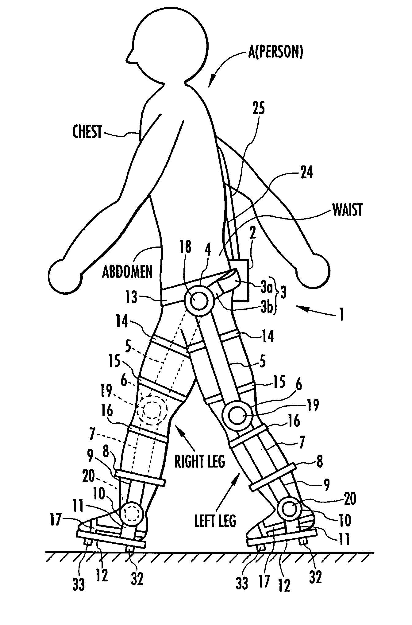
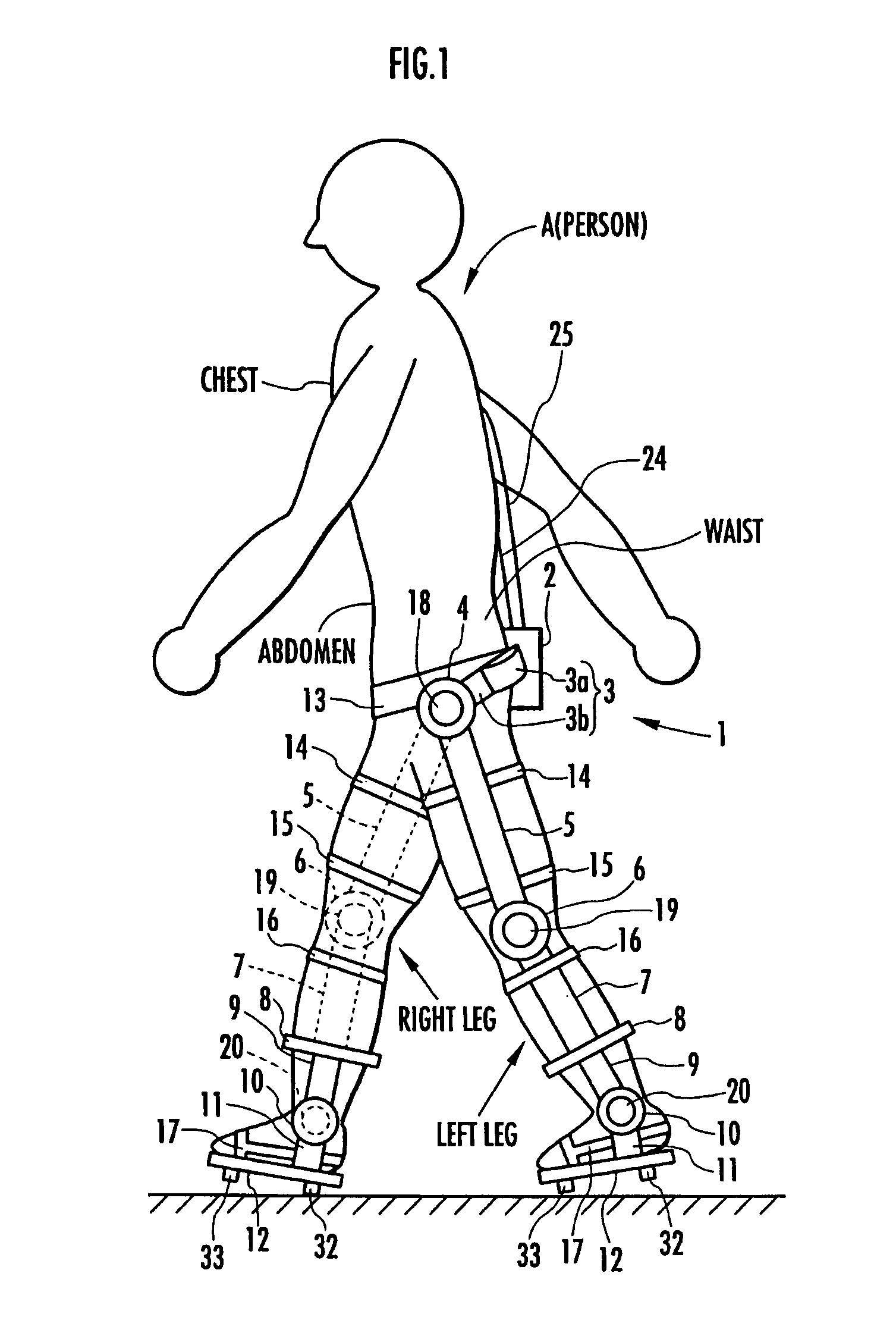
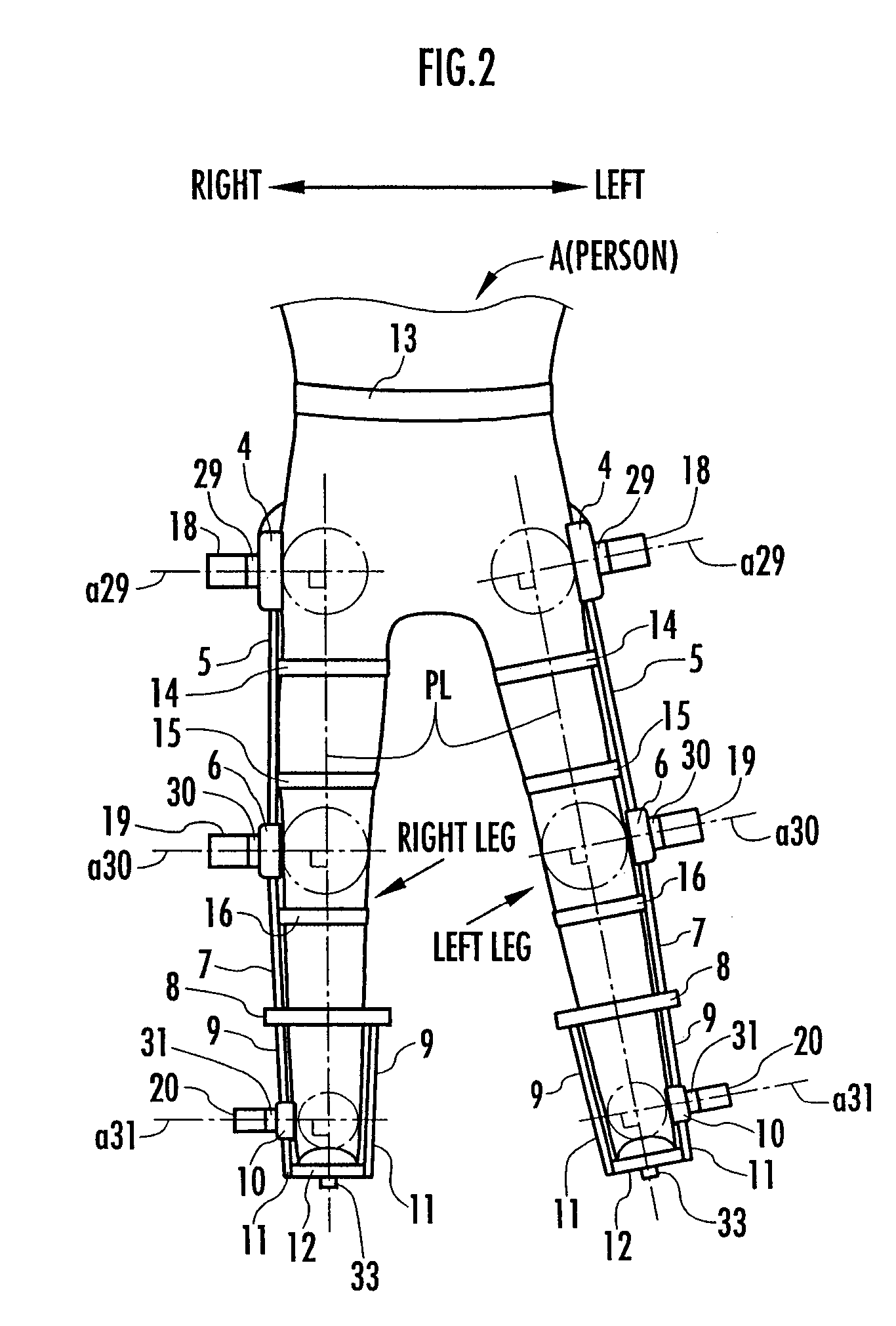
[0049]An embodiment (a first embodiment) of the present invention will be described below by using FIG. 1 to FIG. 19. This embodiment is intended for the first and second features of the present invention. FIG. 1 shows a state where a person A is wearing a leg body exercise assistive apparatus 1 according to this embodiment, by means of a lateral view. FIG. 2 shows a lower part of the body of the person A wearing the leg body exercise assistive apparatus 1, by means of a front view. In FIG. 2, the hip joint, the knee joint, and the ankle joint of each leg of the person A are illustrated in chain-and-dash line circles, respectively, for purposes of the description.

[0050]In these FIG. 1 and FIG. 2, the leg body exercise assistive apparatus 1 (hereinafter, simply referred to as the assistive apparatus 1) includes a sensor box 2 attached to the back of the waist of the person A, a waist link member 3 extended from the sensor box 2 to the place of the hip joint of each leg of the person ...

second embodiment

[0228]While the electric motor 20 is provided in the ankle joint region 10 of the assistive apparatus 1 in the above embodiment, it is possible to omit the electric motor 20 for the ankle joint region 10. In this instance, if the ankle joint region 10 between the foot link member 11 and the second crus link member 9 is formed by a free joint or other rotatable object, the joint moment M(P_crus orthosis) of the knee joint region 6 and the joint moment M(P_thigh orthosis) of the hip joint region 4 may be calculated with the right-hand side of the formula (40) set to “zero” in calculating the joint moments of the assistive apparatus 1. Other things may be the same as in the aforementioned embodiment. The modification described here is referred to as a

third embodiment

[0229]Moreover, for example, if an elastic member such as a spring is disposed between the foot orthosis portion 12 and the second crus link member 9 of the assistive apparatus 1, in other words, if an elastic member 70 such as a spring is disposed between the foot element S9 and the crus element S8 as shown in FIG. 20 when the assistive apparatus 1 is represented in the form of a rigid link model, M(P_foot orthosis) of the formula (40) may be calculated by using a data table or a predetermined arithmetic expression from the detected value of the rotation angle of the ankle joint region 10 and then the knee joint moment M(P_crus orthosis) of the knee joint region 6 and the joint moment M(P_thigh orthosis) of the hip joint region 4 may be calculated by using M(P_foot orthosis). Other things may be the same as those of the aforementioned embodiment. The modification described here is referred to as a

[0230]Verification of effectiveness of the present invention will be described below w...


PUM


Abstract

A generated torque control method for a leg body exercise assistive apparatus enabling a person to make a leg motion in such a feeling that the person is not wearing the leg body exercise assistive apparatus as much as possible by reducing the weight of the leg body exercise assistive apparatus attached to the person acting on the person. On the assumption that a person (A) not wearing the assistive apparatus (1) is making the same motion as a leg motion of the person (A) wearing the leg body exercise assistive apparatus (1) during the leg motion of the person (A), an estimation is made for a person-side joint moment to be generated in each joint of the leg of the person (A), and on the assumption that the assistive apparatus (1) is independently making the same motion as the leg motion, an estimation is made for an apparatus-side joint moment to be generated in the joint regions (4), (6), and (10) of the leg sections of the assistive apparatus (1). The estimated value of the apparatus-side joint moment is considered as a reference torque for torque generation means (18), (19), and (20), and a torque formed by adding a torque according to the estimated value of the person-side joint moment to the reference torque is generated in the torque generation means (18), (19), and (20).

Description

FIELD OF THE INVENTION[0001]The present invention relates to a generated torque control method for a leg body exercise assistive apparatus, which is attached to the legs of a person.BACKGROUND ART[0002]Conventionally, as this type of assistive apparatus, there is an already known apparatus disclosed in Japanese Patent Laid-Open No. 2003-220102 (hereinafter, referred to as “patent document 1”). The assistive apparatus of the patent document 1 includes moment generators on the hip joint, the knee joint, and the ankle joint of each leg of a person, with the moment generators connected to a foot supporting portion for supporting the foot of the person via beams. Moreover, it includes a sensor for detecting a force and moment acting between the foot supporting portion and the ground, a sensor for detecting a tilt angle of a beam, a sensor for detecting a force acting between the assistive apparatus and the person. On the basis of detected outputs of these sensors, a force to be generated...

Claims


Application Information

Patent Timeline
Patent Type & Authority Patents(United States)
IPC IPC(8): A63B21/00A63B22/00A61H3/00A63B23/04A63B23/12A63B24/00B25J13/00B62D57/032
CPCA61H3/00A63B23/04A63B23/12B25J9/1638B62D57/032G05B2219/45109G05B2219/40305A63B2220/54
Inventor KAWAI, MASAKAZUIKEUCHI, YASUSHI
Owner HONDA MOTOR CO LTD
Why Eureka
Try Eureka