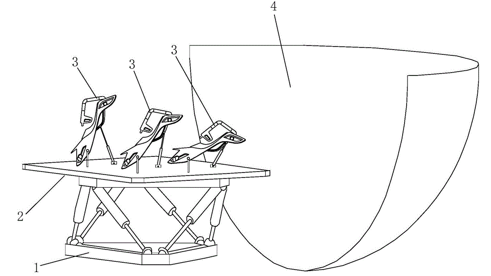
Film-watching aircraft, film-watching system and dome-screen film-watching theater
A technology for aircraft and movie viewing, applied in theaters, podiums, etc., can solve the problems of not being able to meet the needs of simulated flight effects, affecting viewing experience effects, restrictions, etc.
- Summary
- Abstract
- Description
- Claims
- Application Information
AI Technical Summary
Problems solved by technology
Method used
Image
Examples
Embodiment 1
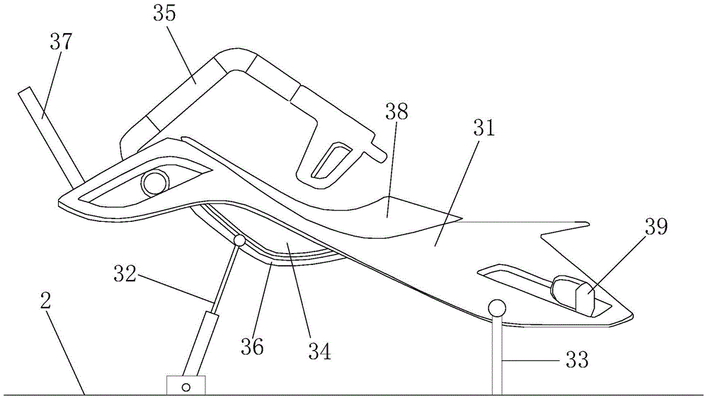
[0047] Please refer to figure 2 , in the viewing aircraft 3 of this embodiment, a track 36 is provided on the rotating bracket 34, and the other end of the telescopic device 32 is rotatably connected to the viewing platform 2, and the rotation axis is parallel to the viewing platform 2. Platform 2;
[0048] The way that the telescopic device 32 connects the rotating bracket 34 and the viewing platform 2 is further configured as:
[0049] During the telescopic movement of the telescopic device 32, one end of the telescopic device 32 can slide or roll along the track 36, and drive the rotating bracket 34 by pushing or pulling the track 36 during sliding or rolling. Rotate about the axis of rotation.
[0050] For how Orbital 36 works, please refer to Figure 6 and Figure 7 , the present embodiment provides a feasible solution, which can also be adopted in embodiments 2 to 4. A space for the roller 321 to roll is formed between the inner track ring 362 and the outer track ri...
Embodiment 2
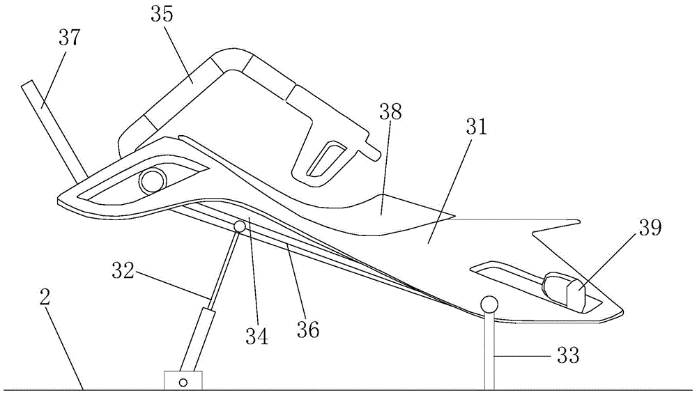
[0057] Please refer to image 3 , The main difference between this embodiment and Embodiment 1 is: in this embodiment, the track is a straight track. It can be seen that no matter what the surface shape of the rotating bracket 34 is or what the shape of the track arranged on it is, it is one of the solutions that the present invention seeks to protect. According to the requirements of different rotation effects, those skilled in the art can think of how to further arrange the track. The shape, in other words, the fact that the track is introduced into the invention, especially its combination with the rectilinear movement of the telescoping device 2 and thus the rotation, should be non-obvious, and it is by no means unobtrusive to a person skilled in the art based on the prior art can think of.
Embodiment 3
[0059] Please refer to Figure 4 The main difference between this embodiment and Embodiment 1 is: in this embodiment, one end of the telescopic device 32 is rotatably connected to the rotating bracket 34, and the rotation axis is parallel to the viewing platform 2;
[0060] The way that the telescopic device 32 is connected to the rotating bracket and the viewing platform is further configured as:
[0061] During the telescopic movement of the telescopic device, one end of the telescopic device 32 rotates around the rotation axis by pushing or pulling the rotating bracket 34, and the other end of the telescopic device 32 slides along the viewing platform 2 or scroll.
[0062] In other words, in Embodiments 1 and 2, the connection point between the telescopic device 32 and the rotating bracket 34 is used as a moving point, and in this embodiment, the connection point between it and the rotating bracket 34 is used as a fixed point, and the connection point between it and the vi...
PUM
 Abstract
Description
Claims
Application Information
 - R&D Engineer
- R&D Manager
- IP Professional
- Industry Leading Data Capabilities
- Powerful AI technology
- Patent DNA Extraction
Browse by: Latest US Patents, China's latest patents, Technical Efficacy Thesaurus, Application Domain, Technology Topic, Popular Technical Reports.
© 2024 PatSnap. All rights reserved.Legal|Privacy policy|Modern Slavery Act Transparency Statement|Sitemap|About US| Contact US: help@patsnap.com


