Supercharge Your Innovation With Domain-Expert AI Agents!

A semi-automatic ultra-narrow gap mag/mig welding torch

A narrow gap, semi-automatic technology, applied in the direction of welding rod characteristics, welding equipment, arc welding equipment, etc., can solve the problems of infeasibility, unseen, not closed, and can be carried out from the outside or the reverse side of the narrow gap groove, etc.

Inactive Publication Date: 2018-01-09
武汉纳瑞格智能设备有限公司
View PDF6 Cites 0 Cited by
  • Summary
  • Abstract
  • Description
  • Claims
  • Application Information

AI Technical Summary

Problems solved by technology

Due to the substantial reduction in the assembly gap of the weldment groove, the welding groove under this new process is actually a very narrow and deep groove, and the weldment is spot-fixed by semi-automatic welding in the assembly stage before welding. Assembly is extremely infeasible, because the outer diameter of the nozzle of the traditional semi-automatic gas shielded welding torch is much larger than the gap of the ultra-narrow gap welding groove, so it cannot be inserted into the groove for spot welding; It can be barely tack welded, but the slag is extremely difficult to remove
When some weldments belong to open structures, tack welding can be performed from the reverse side of the narrow gap groove, but for closed box structures, often the main welds are all fillet joints, and the front three square webs and flanges It is not closed during assembly, and tack welding can be performed from the outside or the reverse side of the narrow gap groove, but after the last party (4th party) is assembled, its tack welding can only be done by extending the welding torch from outside the groove to the root of the assembly gap for tack welding, however The existing technology does not have this technology at all, which has led to the fact that so far, there is no precedent for the application of narrow-gap or ultra-narrow-gap MAG / MIG welding technology for the four main welding seams of heavy-duty box structures.

Method used


Image

  • A semi-automatic ultra-narrow gap mag/mig welding torch
  • A semi-automatic ultra-narrow gap mag/mig welding torch
  • A semi-automatic ultra-narrow gap mag/mig welding torch

Examples


Embodiment

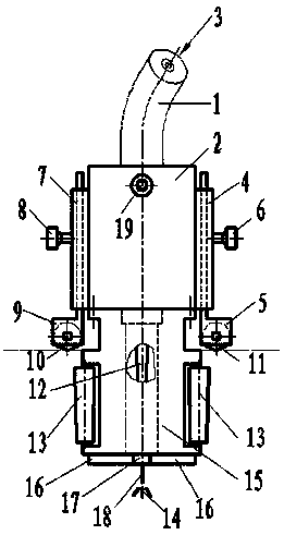
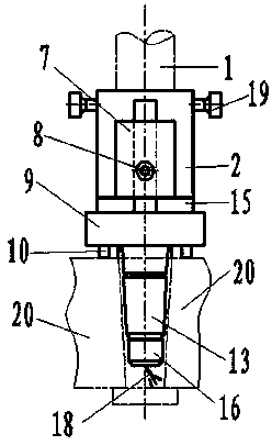
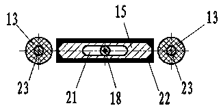
[0017] The semi-automatic ultra-narrow gap MAG / MIG welding torch of the present invention is mainly composed of four parts: transition torch base 2, ultra-narrow gap MAG / MIG welding nozzle 15, ultra-narrow gap seam tracking device and ultra-narrow gap groove depth adjustment device. The transition gun seat 2 is a special structure in which the wire feeding, gas feeding and contact tip structure of the traditional gooseneck semi-automatic welding torch transitions to the technology of the present invention. The shape is a cube, and the inside is a stepped round hole; The diameter of the hole is slightly larger than the diameter of this part of the traditional semi-automatic gas shielded welding torch; the diameter D of the round hole in the middle and lower part is slightly larger than the structural diameter φ of the traditional semi-automatic gas shielded welding torch after removing the nozzle, D=φ+0.1mm~0.3mm is enough ; The bottom is a waist circular boss, and the left and ...


PUM

PropertyMeasurementUnit
thicknessaaaaaaaaaa
thicknessaaaaaaaaaa

Abstract

The invention belongs to the field of welding technology, and relates to a semi-automatic ultra-narrow gap MAG / MIG welding torch, which includes a transition gun seat, an ultra-narrow gap MAG / MIG welding nozzle connected to the bottom end of the transition gun seat, and an ultra-narrow gap MAG / MIG welding nozzle. Ultra-narrow gap seam tracking devices on both sides of the welding nozzle and ultra-narrow gap groove depth adjustment devices on both sides of the transition gun seat. The present invention makes it possible to perform positioning welding on the root of the groove with the traditional semi-automatic gas shielded welding process during the assembly and positioning welding of the narrow gap and ultra-narrow gap MAG / MIG welding groove; secondly, the present invention can be used for inconvenient use Fully mechanized and fully automated welding of irregular narrow gaps and ultra-narrow gap MAG / MIG short welds; finally, the ultra-narrow gap MAG / MIG welding nozzle of the present invention can also be used for automated narrow gaps after the self-circulating water cooling function is added. Gap and ultra-narrow gap MAG / MIG welding applications.

Description

technical field [0001] The invention belongs to the field of welding technology and relates to a semi-automatic ultra-narrow gap MAG / MIG welding torch. Background technique [0002] Narrow-gap MAG / MIG welding and ultra-narrow-gap MAG / MIG welding technology are widely used in industrial production. This technology can be used in industrial production. In addition to the above-mentioned key technologies, it must also be solved in the narrow gap and ultra-narrow gap conditions, and the welding parts can be assembled conveniently and quickly before welding. Due to the substantial reduction in the assembly gap of the weldment groove, the welding groove under this new process is actually a very narrow and deep groove, and the weldment is spot-fixed by semi-automatic welding in the assembly stage before welding. Assembly is extremely infeasible, because the outer diameter of the nozzle of the traditional semi-automatic gas shielded welding torch is much larger than the gap of the ...

Claims


Application Information

Patent Timeline
Patent Type & Authority Patents(China)
IPC IPC(8): B23K9/28B23K9/26B23K9/173B23K9/127
CPCB23K9/1278B23K9/173B23K9/26B23K9/28B23K9/285
Inventor 张富巨何浩王宇飞郭嘉琳张国栋
Owner 武汉纳瑞格智能设备有限公司
Features
  • R&D
  • Intellectual Property
  • Life Sciences
  • Materials
  • Tech Scout
  • Unparalleled Data Quality
  • Higher Quality Content
  • 60% Fewer Hallucinations
Learn More