Bending device and method based on positioning clamping control and feedback control

A processing device and feedback control technology, applied in the field of sheet metal processing, can solve problems such as empty folding and excessive bending, prone to deflection, deformation of the clamping place, etc., achieve convenient height and angle, reduce cracks and burrs, prevent The effect of overbending

Inactive Publication Date: 2015-10-07
SUZHOU BIANTONG SENSING TECH
View PDF6 Cites 2 Cited by
  • Summary
  • Abstract
  • Description
  • Claims
  • Application Information

AI Technical Summary

Problems solved by technology

[0003] At present, some small bending machines have appeared on the market, which can realize simple bending processing of plates, but they have the following disadvantages: the bending torque is set by the experience of workers during work, and cannot be adjusted in real time according to the thickness of the plate, and the quality of plate processing is not good. High, there are crack defects in the bent plate; the bent plate can only be detected by naked eyes, the detection is inaccurate and the effect is not good; the lack of angle control device is prone to excessive bending, and there are safety hazards; Afterwards, due to cracks and burrs on the concave surface of the sheet material, further processing is required, resulting in a long processing cycle; the workpiece to be processed is manually adjusted and clamped, and the clamping force is often too large or too small, resulting in loosening of the processed part during bending Or the deformation of the clamping part is too large; the lack of positioning and bending angle control devices is prone to bending deviation, empty folding and excessive bending, posing safety hazards

Method used


Image

  • Bending device and method based on positioning clamping control and feedback control
  • Bending device and method based on positioning clamping control and feedback control
  • Bending device and method based on positioning clamping control and feedback control

Examples


Embodiment Construction

[0027] The specific implementation manner of the present invention will be described below in conjunction with the accompanying drawings.

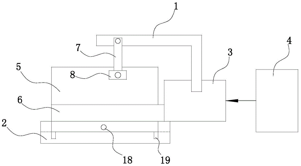
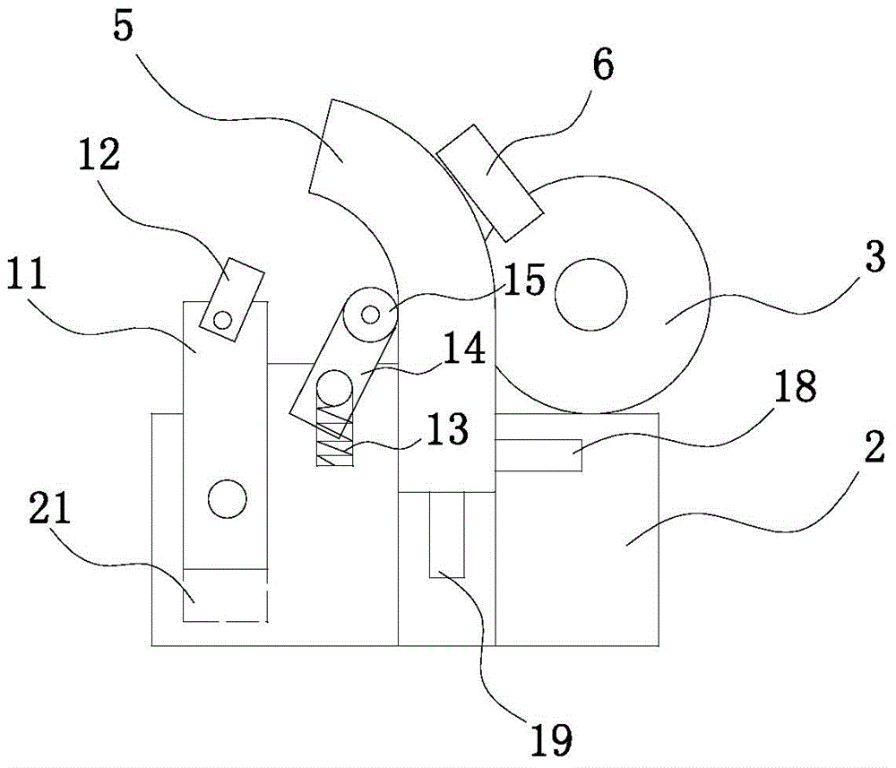
[0028] Such as Figure 1 to Figure 4 As shown, the bending processing device based on positioning clamping control and feedback control in this embodiment includes a drive motor 3 installed on the frame 1, a clamping and fixing seat 2 and a host 4 that controls the drive motor 3, and the drive motor 3 The bending shaft 6 is installed on the motor shaft, and the workpiece 5 is installed on the clamping seat 2;

[0029] It also includes a capacitive induction thickness detector 8 installed on the frame 1 by means of the first bracket 7, a roller 15 installed on the clamping and fixing seat 2, a proximity switch 12, a detection feedback device and a controller 10 connected to the host 4, The roller 15 is rotatably connected to the upper end surface of the adjustment plate 14, the lower end surface of the adjustment plate 14 is installed in t...


PUM


Abstract

The invention relates to a bending device and method based on positioning clamping control and feedback control. The device comprises a driving motor arranged on a machine frame, a clamping and fixing base and a main unit, wherein a bending shaft is installed on the driving motor, and a part to be machined is arranged on the clamping and fixing base. The device further comprises a capacitive sensing thickness detector, a roller, a proximity switch, a pressure sensor, a detection feedback device and a controller, wherein the roller and the proximity switch are arranged on the bent side of the part to be machined, the detection feedback device comprises an ultrasonic crack detector arranged on the clamping and fixing base, and the capacitive sensing thickness detector, the proximity switch, the pressure sensor and the ultrasonic crack detector are all connected with the main unit. By combining crack detection with roller extrusion friction for bending, the number of cracks is reduced greatly, and machining quality is improved; the proximity switch is arranged to automatically control bending angle, so that excessive bending is prevented; the pressure sensor is adopted for controlling clamping pressure and positioning, so that a metal plate is prevented from deformation or disengagement and machining reliability is improved.

Description

technical field [0001] The invention relates to the technical field of sheet metal processing, in particular to a sheet metal bending device. Background technique [0002] Currently used sheet metal bending machine, commonly used two types of organic pillow hydraulic, mechanical bending machine is to use the motor through a series of gear transmission and eccentric wheel to realize the up and down movement of the working joint. The hydraulic bending machine is realized by using a hydraulic cylinder and a complete set of oil circuit control components. These bending machines play an important role in the mass production of large enterprises, but due to their high price and complex structure, their popularization is limited. With the development of the commodity economy, there are more and more stamping parts for small commodities for daily use. Small enterprises and even self-employed households urgently need sheet metal bending machines with low price and simple structure. ...

Claims


Application Information

Patent Timeline
Patent Type & Authority Applications(China)
IPC IPC(8): B21D5/04B21D37/10
CPCB21D5/04B21D5/004B21D5/006
Inventor 不公告发明人
Owner SUZHOU BIANTONG SENSING TECH
Why Eureka
Try Eureka