
Automatic conveying die punching machine for forming keel metal sheet

An automatic conveying and sheet metal technology, which is applied in the direction of metal processing equipment, forming tools, feeding devices, etc., can solve the problems of multi-manpower conveying, simple process, time-consuming and labor-intensive, etc.

Active Publication Date: 2015-10-14
南通北外滩建设工程有限公司
View PDF10 Cites 3 Cited by
  • Summary
  • Abstract
  • Description
  • Claims
  • Application Information

AI Technical Summary

Problems solved by technology

[0002] Metal sheets need to be installed at both ends of the keel, and the metal sheets are small in size and need to be stamped multiple times to form. The existing punching machine has a simple process, requires multiple punching machines, and requires more manpower for transportation and movement. Time-consuming

Method used


Image

  • Automatic conveying die punching machine for forming keel metal sheet
  • Automatic conveying die punching machine for forming keel metal sheet

Examples


Embodiment Construction

[0022] The present invention will be further described in conjunction with specific embodiment now. These drawings are simplified schematic diagrams only to illustrate the basic structure of the present invention in a schematic way, so they only show the components relevant to the present invention.

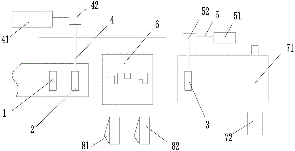
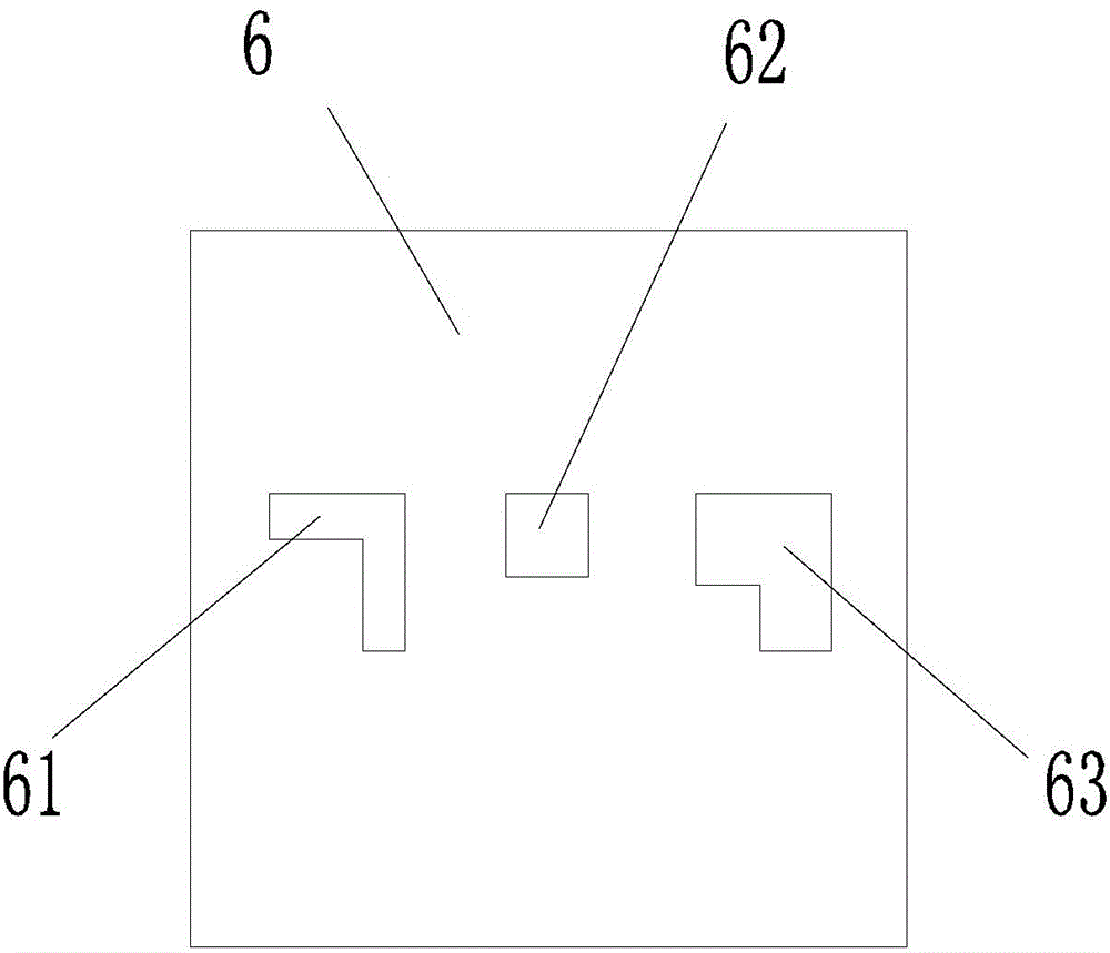
[0023] Such as figure 1 figure 2 As shown, an automatic conveying die machine for keel metal sheet forming, which sequentially includes a front conveying area, a punching die area, a rear conveying area, and a rear coiling area.

[0024] The front conveying area includes the first cylinder 1 and the second cylinder 2. The first cylinder 1 and the second cylinder 2 carry out asynchronous downward pressure on the conveying material. The second cylinder 2 is connected to drive the second cylinder 2 to move along the direction of material movement. The first quantitative moving mechanism 4; the rear conveying area includes a third cylinder 3, and the third cylinder 3 and the secon...


PUM


Abstract

The invention relates to an automatic conveying die punching machine for forming a keel metal sheet. The automatic conveying die punching machine sequentially comprises a front conveying area, a die punching area, a rear conveying area and a rear rolling area. The front conveying area comprises a first air cylinder and a second air cylinder. The first air cylinder and the second air cylinder carry out asynchronous pressing on conveyed raw materials. The second air cylinder is connected with a first quantitative moving mechanism for driving the second air cylinder to do motion in the moving direction of the raw materials. The rear conveying area comprises a third air cylinder. The third air cylinder and the second air cylinder carry out synchronous pressing on the conveyed raw materials. The third air cylinder is connected with a second quantitative moving mechanism for driving the third air cylinder to do motion in the moving direction of the raw materials. The second air cylinder and the third air cylinder synchronously move in the same direction. By means of asynchronous pressing on the keel metal sheet, a keel of the keel metal sheet can be constantly punched through an upper die without participation of manpower, and the die punching efficiency of the die punching machine is improved.

Description

technical field [0001] The invention relates to an automatic conveying die machine for forming keel metal sheets. Background technique [0002] Metal sheets need to be installed at both ends of the keel, and the metal sheets are small in size and need to be stamped many times before they can be formed. The existing punching machine has a simple process, requires multiple punching machines, and requires more manpower for transportation and movement. Time-consuming. Contents of the invention [0003] The technical problem to be solved by the present invention is to overcome the deficiencies of the prior art and provide an automatic conveying punching machine for forming keel metal sheets. [0004] The technical solution adopted by the present invention to solve the technical problem is: an automatic conveying punching machine for forming keel metal sheets, which sequentially includes a front conveying area, a punching die area, a rear conveying area, and a rear coiling area...

Claims


Application Information

Patent Timeline
Patent Type & Authority Applications(China)
IPC IPC(8): B21D28/02B21D35/00B21D43/05B21D37/10
CPCB21D28/14B21D35/002B21D37/10B21D43/05
Inventor 沈栋明沈晓燕
Owner 南通北外滩建设工程有限公司
Learn More