
Method for machining spiral groove
A processing method and a technology of spiral grooves, which are applied in the field of spiral groove processing, can solve the problems of low processing efficiency and achieve the effects of increasing processing speed, less wear, and reducing procedures
- Summary
- Abstract
- Description
- Claims
- Application Information
AI Technical Summary
Problems solved by technology
Method used
Image


Examples
Embodiment 1
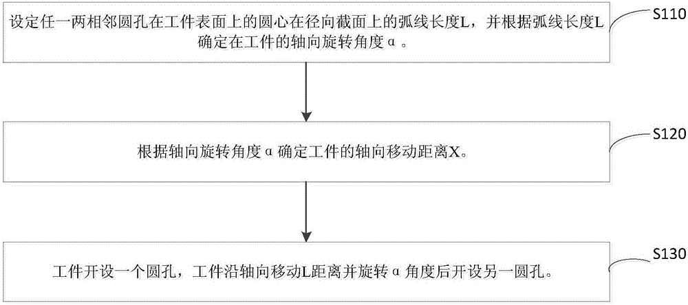
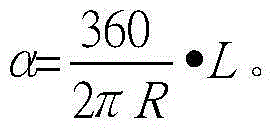
[0052]The VF-3 machine tool processes spiral grooves on the surface of the workpiece. The outer circle radius R of the workpiece is φ17mm, the pitch of the spiral groove is 12mm, the groove depth is 6mm, and the groove width is 3mm. During the processing, after the workpiece is opened with a round hole with a diameter of 3 mm, another round hole is opened after the workpiece is moved 1.33 mm in the axial direction and rotated at an angle of 40° to form multiple round holes set at intervals, and then the drill bit is used to remove the fan-shaped excess. amount to form a helical thick groove. Use a φ3mmxx milling cutter to finish the helical rough groove to obtain the helical groove. In 8 hours, a total of 21 workpieces were processed.
Embodiment 2
[0054] The difference between embodiment 2 and embodiment 1 is that another circular hole is opened after the workpiece moves 0.67 mm in the axial direction and rotates 20 degrees. In 8 hours, a total of 16 workpieces were machined. Compared with the workpiece processed in Example 1, the surface roughness is slightly lower.
Embodiment 3
[0056] The difference between embodiment 3 and embodiment 1 is that another circular hole is opened after the workpiece is moved 2 mm in the axial direction and rotated by 60 degrees. In 8 hours, a total of 14 workpieces were machined. Compared with the workpiece processed in Example 1, the surface roughness is slightly lower.
PUM
 Abstract
Description
Claims
Application Information