
Mining hydraulic support assembly platform
A hydraulic support and platform technology, which is applied in mine roof support, mining equipment, earthwork drilling and mining, etc., can solve the problems of limited lifting weight, limited lifting height of components, difficult positioning, etc., achieve high degree of automation, reduce labor intensity, save labor effect
- Summary
- Abstract
- Description
- Claims
- Application Information
AI Technical Summary
Problems solved by technology
Method used
Image

Examples
Embodiment Construction
[0037] In order to make the purpose, technical solutions and beneficial effects of the present invention more clear, the following will further describe the implementation of the present invention in detail in conjunction with the accompanying drawings.
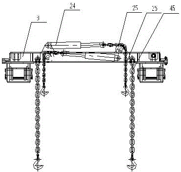
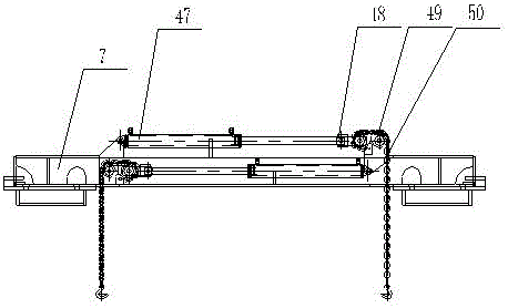
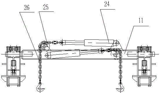
[0038] Such as figure 1 , figure 2 , image 3 As shown, the present invention provides a mining hydraulic support assembly platform, including two sets of scissor lifting devices and two groups of cantilever lifting devices, the two groups of scissor lifting devices are respectively parallel first scissor lifting devices 1. The second scissor lifting device 2, two groups of cantilever lifting devices are the first parallel cantilever lifting device 3, the second cantilever lifting device 4, the top of the first scissor lifting device 1 and the second The first fixed beam 5, the second fixed beam 6, the third fixed beam 7, the first sliding beam 8, the second sliding beam 9 are connected between the tops of the two scissor ...
PUM
 Abstract
Description
Claims
Application Information