pneumatic tire

A technology for pneumatic tires and tires, applied in the direction of pneumatic tires, tire parts, tire tread/tread pattern, etc., can solve the problem of unclear tire braking performance and rotation performance, no anisotropy of the pattern, and no variety of patterns Anisotropy and other issues can be improved to improve braking performance and spin performance on ice

Inactive Publication Date: 2018-08-24
THE YOKOHAMA RUBBER CO LTD
View PDF9 Cites 0 Cited by
  • Summary
  • Abstract
  • Description
  • Claims
  • Application Information

AI Technical Summary

Problems solved by technology

In addition, in the pneumatic tire disclosed in Patent Document 2, although the shape of each block has anisotropy in the tire width direction, the pattern of the block group composed of a plurality of blocks is not consistent when viewed from the entire tread pattern. anisotropy
[0011] Thus, in the techniques disclosed in Patent Documents 1 and 2, the pattern of the block group does not have anisotropy at least as viewed from the entire tread pattern, so it is unclear whether the tire can perform braking at a high level on ice. Performance and Rotational Performance

Method used


Image

  • pneumatic tire
  • pneumatic tire
  • pneumatic tire

Examples


Embodiment approach 1

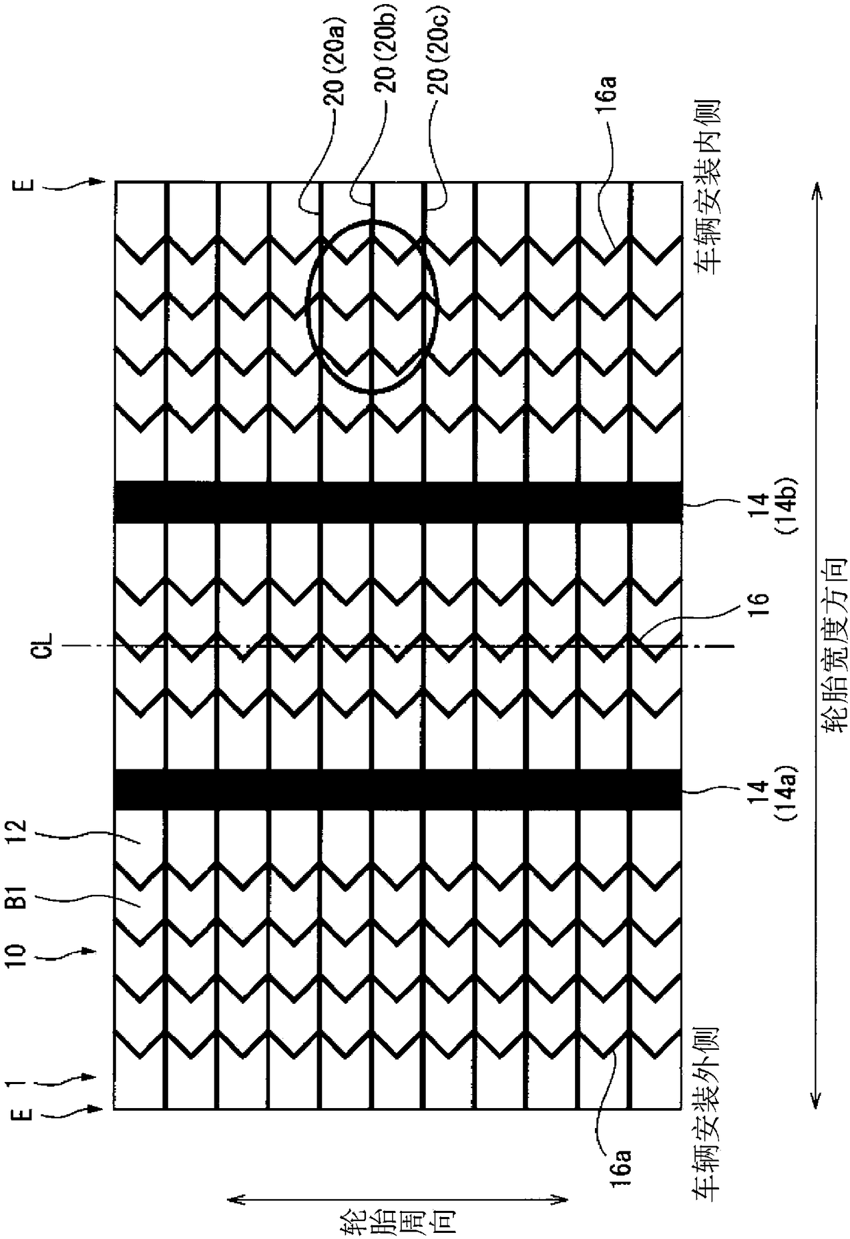
[0026] Basic Embodiment 1 is an embodiment of a pneumatic tire in which a vehicle mounting direction is specified. figure 1 It is a plan view showing the tread portion of the pneumatic tire according to the embodiment of the present invention. The tread portion 10 of the pneumatic tire 1 shown in the figure is made of rubber material (tread rubber), is exposed on the outermost side in the tire radial direction of the pneumatic tire 1 , and its surface constitutes the outline of the pneumatic tire 1 . The surface of the tread portion 10 constitutes a tire tread, that is, a surface on which the vehicle (not shown) on which the pneumatic tire 1 is mounted comes into contact with the ground when running.

[0027] Such as figure 1 As shown, the tread surface 12 is respectively provided with grooves 14 and 16 extending in the tire circumferential direction and a groove 20 inclined relative to the tire circumferential direction, forming the tread pattern shown in the figure. The sp...

Embodiment approach 2

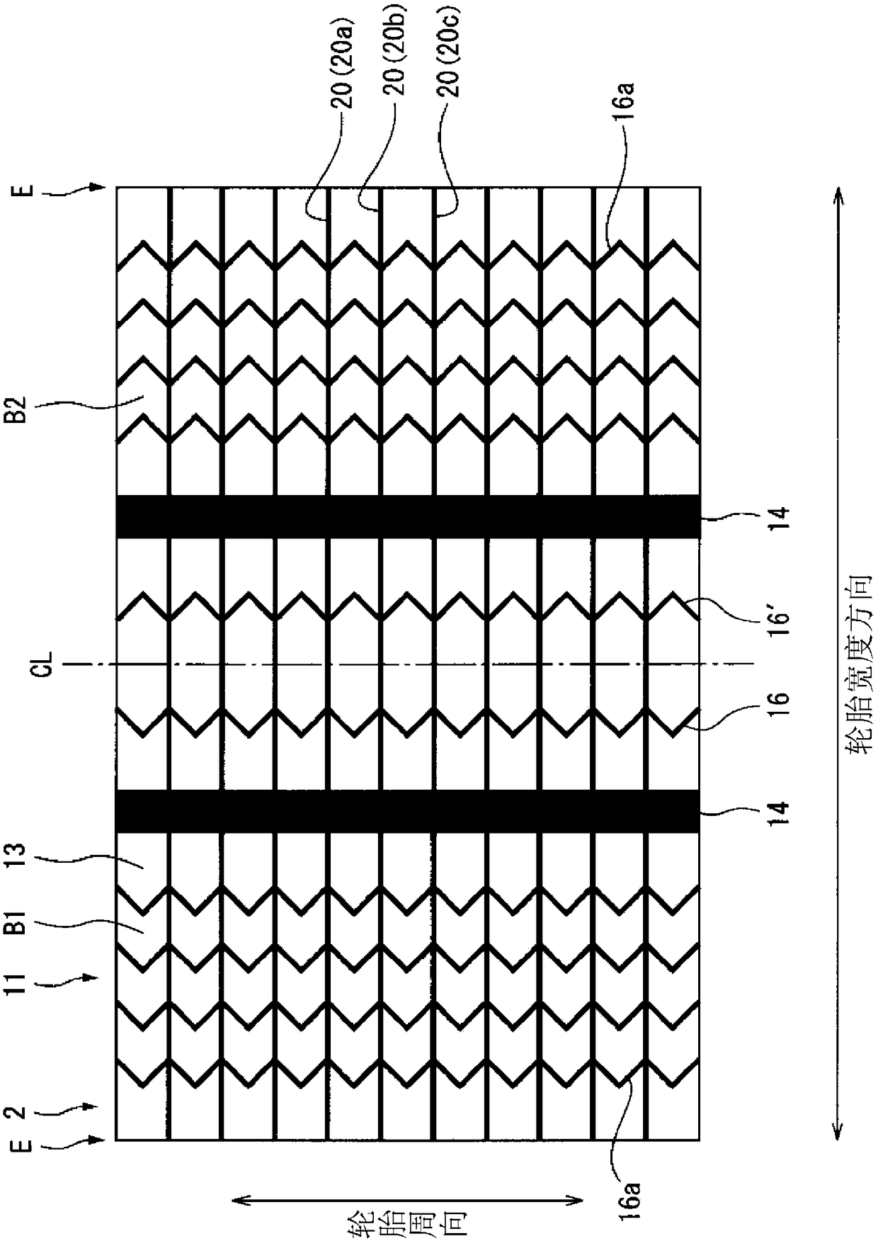
[0050] Basic Embodiment 2 is an embodiment of a pneumatic tire in which a vehicle mounting direction is not specified. image 3 It is a plan view showing the tread portion of the pneumatic tire according to the embodiment of the present invention. The pneumatic tire 1 shown in this figure has a tread pattern that is line-symmetric with respect to the tire equatorial plane CL. The reference symbols shown in the figure, with figure 1 The same reference symbols as those shown indicate the same figure 1 The constituent elements shown are the same as the constituent elements.

[0051] and figure 1 The basic embodiment 1 shown is the same, image 3 The tread portion 11 of the illustrated pneumatic tire 2 is made of rubber material (tread rubber), is exposed on the outermost side in the tire radial direction of the pneumatic tire 2 , and its surface constitutes the outline of the pneumatic tire 2 . The surface of the tread portion 11 is formed as a tread surface 13 , that is, a ...

Embodiment approach

[0056] Next, additional embodiments 1 to 10, which can be arbitrarily implemented with respect to the above-mentioned basic embodiment of the pneumatic tire according to the present invention, will be described.

[0057] (additional embodiment 1)

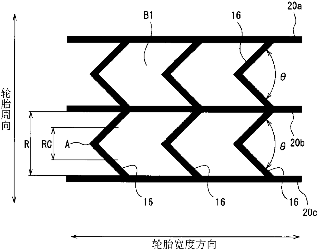
[0058] In the basic embodiment (basic embodiment 1, 2), preferably figure 1 , 3 The intervals between the narrow grooves 20 in the middle width direction are 0.8 times or more and 1.5 times or less the intervals between the circumferential thin grooves 16 ( 16 ′), respectively (additional embodiment 1).

[0059] Here, the interval between the narrow grooves 20 in the width direction means, for example, the grooves of the narrow grooves 20a, 20b adjacent in the circumferential direction of the tire (or the narrow grooves 20b, 20c adjacent in the circumferential direction of the tire). The distance between the centerlines in the width direction. Likewise, the interval between the circumferential narrow grooves 16 ( 16 ′) refers to ...


PUM


Abstract

The present invention provides a pneumatic tire with improved driving performance and rotational performance on ice. The circumferential direction fine grooves (16) are arranged at a tire width direction density of 0.06 lines / mm or more and 0.2 lines / mm or less. The narrow grooves (20) in the width direction extend at an angle of -45° or more and +45° or less with respect to the tire width direction. The circumferential fine groove (16) has at least one curved portion. The bending angle of the said bending part is 40 degrees or more and 160 degrees or less.

Description

technical field [0001] The present invention relates to a pneumatic tire with improved braking performance and spin performance on ice. Background technique [0002] Conventionally, techniques for improving ice performance (braking performance and driving performance) of studless tires are known (for example, refer to Patent Documents 1 and 2). The pneumatic tires disclosed in Patent Documents 1 and 2 both have a tread pattern in which a plurality of blocks are densely arranged in a grid pattern. [0003] prior art literature [0004] patent documents [0005] Patent Document 1: International Publication No. 2010 / 032606 [0006] Patent Document 2: Japanese Patent Laid-Open No. 2008-162298 [0007] Summary of the invention [0008] The problem to be solved by the invention [0009] In general, when only the resistance against external force in a specific direction is increased by imparting anisotropy to the shape of the block, there is a tendency that a specific perform...

Claims


Application Information

Patent Timeline
Patent Type & Authority Patents(China)
IPC IPC(8): B60C11/11B60C5/00B60C11/04B60C11/12B60C11/13
CPCB60C11/04B60C2011/1209B60C2011/1213B60C11/1236B60C2011/1245B60C2011/036B60C11/0304B60C2011/1295B60C2011/0346B60C2011/0348B60C11/11B60C11/12B60C11/0306B60C11/0327B60C2011/0353
Inventor 加贺谷圭佑
Owner THE YOKOHAMA RUBBER CO LTD
Why Eureka
Try Eureka