Multi-coordinate machining center combination method based on vision and movable mechanical arm

A technology of moving manipulators and combining methods, applied in the fields of machinery and information, can solve the problem of not being able to directly combine multi-coordinate machining centers, etc.

Active Publication Date: 2015-11-18
XIAN FEISIDA AUTOMATION ENG
View PDF6 Cites 6 Cited by
  • Summary
  • Abstract
  • Description
  • Claims
  • Application Information

AI Technical Summary

Problems solved by technology

[0006] In order to overcome the major technical defect that the mobile robot and the boring, milling, drilling and other machine tools cannot be directly combined into a multi-coordinate machining center, this invention proposes a multi-coordinate machining center combination method based on vision and mobile manipulator. Robotic arm and boring machine, milling machine, and drilling machine set up processing tasks and procedures; set up the track and fixture of the mobile arm, and install CCD and laser distance measuring or connect cameras on the mobile arm, and face the track of the mobile arm on the boring machine, milling machine, and drilling machine Set multiple light marking points, and then the multi-joint control of the mobile robot arm will make the mobile robot arm move the workpiece to the predetermined position. At the same time, it will perform online positioning monitoring and error correction during the processing process, and give a fault alarm to the processing system. , realized the combination of multi-coordinate machining centers, and solved the major technical problem of directly combining mobile robots with boring, milling, drilling and other machine tools into multi-coordinate machining centers

Method used


Image

  • Multi-coordinate machining center combination method based on vision and movable mechanical arm
  • Multi-coordinate machining center combination method based on vision and movable mechanical arm
  • Multi-coordinate machining center combination method based on vision and movable mechanical arm

Examples


Embodiment Construction

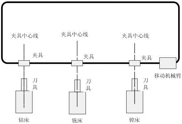
[0022] refer to figure 1 .

[0023] (1) Set processing tasks and procedures on the mobile manipulator, boring machine, milling machine, and drilling machine; set the track of the mobile manipulator so that the mobile manipulator can move on the track; arrange the boring machines, milling machines, Drilling machine, so that the boring machine, milling machine, and drilling machine tool face the track of the mobile manipulator and are perpendicular to the track. The vertical line is used as the clamp centerline of the mobile manipulator. When the gravity center line of the mobile manipulator is in line with the boring machine, milling machine or When the centerlines of the fixtures in front of the drilling machine intersect, the mobile robot arm stops moving and is locked by the fixture. After multi-coordinate alignment and accurate positioning, the processing is carried out, and the accumulated error correction of online processing is performed. After the processing is complete...


PUM


Abstract

The invention provides a multi-coordinate machining center combination method based on vision and a movable mechanical arm, and aims to overcome the large technical defect that a movable robot, a boring machine, a milling machine, a drilling machine and the like cannot be directly combined into a multi-coordinate machining center. The method comprises the steps that machining tasks and procedures are set on the movable mechanical arm, the boring machine, the milling machine and the drilling machine; a movable mechanical arm rail and clamps are arranged, a CCD and a laser ranging device or a connect camera is arranged on the movable mechanical arm, and a plurality of light mark points are arranged on the boring machine, the milling machine and the drilling machine towards the movable mechanical arm rail; then a workpiece to be machined is moved to a preset position by the movable mechanical arm through multi-joint control of the movable mechanical arm; and meanwhile, online locating monitoring and error correction are carried out in the machining process, fault alarms are given to a machining system, and multi-coordinate machining center combination is achieved. The great technical aim of directly combining the mobile robot, the boring machine, the milling machine, the drilling machine and the like into the multi-coordinate machining center is achieved.

Description

technical field [0001] The invention relates to a multi-coordinate machining center, a mobile robot and a visual perception method, in particular to a combination method of a multi-coordinate machining center based on vision and a mobile robot arm, and belongs to the field of machinery and information technology. Background technique [0002] The equipment manufacturing industry is known as the "industrial mother machine" and is the cornerstone of the manufacturing industry. All kinds of equipment and facilities required for industrial modernization are inseparable from high-end processing centers and basic manufacturing equipment. Their performance, quality and possession have become an important symbol for measuring a country's industrialization level and comprehensive national strength; looking at the world, the United States, Japan China, Germany and other powerful countries in the world's equipment manufacturing industry all attach importance to the control of high-end ...

Claims


Application Information

Patent Timeline
Patent Type & Authority Applications(China)
IPC IPC(8): B23Q17/24
CPCB23Q17/2428
Inventor 史忠科
Owner XIAN FEISIDA AUTOMATION ENG
Why Eureka
Try Eureka